Method and apparatus of controlling uplink power for multi-cell cooperative system

a cooperative system and power supply technology, applied in power management, multi-antenna systems, site diversity, etc., can solve the problems of increasing the energy consumption of ms, inappropriate direct use of the above conventional control method of ul power, and waste of power consumption of mobile stations. , to achieve the effect of effectively controlling transmitting power, avoiding unnecessary waste of power consumption of mobile stations, and avoiding excessive interferen

Inactive Publication Date: 2011-07-14
LG ELECTRONICS INC
View PDF4 Cites 43 Cited by
  • Summary
  • Abstract
  • Description
  • Claims
  • Application Information

AI Technical Summary

Benefits of technology

[0019]According to an exemplary embodiment of the present invention, uplink power can be controlled by considering cooperative communication of a plurality of base stations in a multi-cell cooperative radio communication system. In particular, uplink power is properly regulated by considering a neighboring base station even if a downlink signal received from a base station in a cell to which a mobile station belongs has a great path-loss. Thus, it is possible to avoid unnecessary waste of power consumption of the mobile station when uplink transmit power is excessively increased or it is possible to avoid excessive interference on communication of a neighbor mobile station. In addition, according to an embodiment of the present invention, uplink transmit power can be adaptively controlled using a method of performing cooperative communication between base stations, and thus transmit power can be effectively controlled.

Problems solved by technology

However, cooperative communication between BSs is not considered in the conventional method of controlling UL power.
Therefore, direct use of the aforementioned conventional method of controlling UL power is inappropriate in an environment where a UL signal is transmitted in cooperation of several BSs.
The increase in the UL power of the MS results in the increase in energy consumption of the MS.
In addition, a signal transmitted with high power may have an adverse effect on communication of other MSs.

Method used


Image

  • Method and apparatus of controlling uplink power for multi-cell cooperative system
  • Method and apparatus of controlling uplink power for multi-cell cooperative system
  • Method and apparatus of controlling uplink power for multi-cell cooperative system

Examples


Embodiment Construction

[0025]Hereinafter, the present invention will be described in detail by explaining exemplary embodiments of the invention with reference to the accompanying drawings. The same reference numbers will be used throughout the drawings to refer to the same constitutional elements.

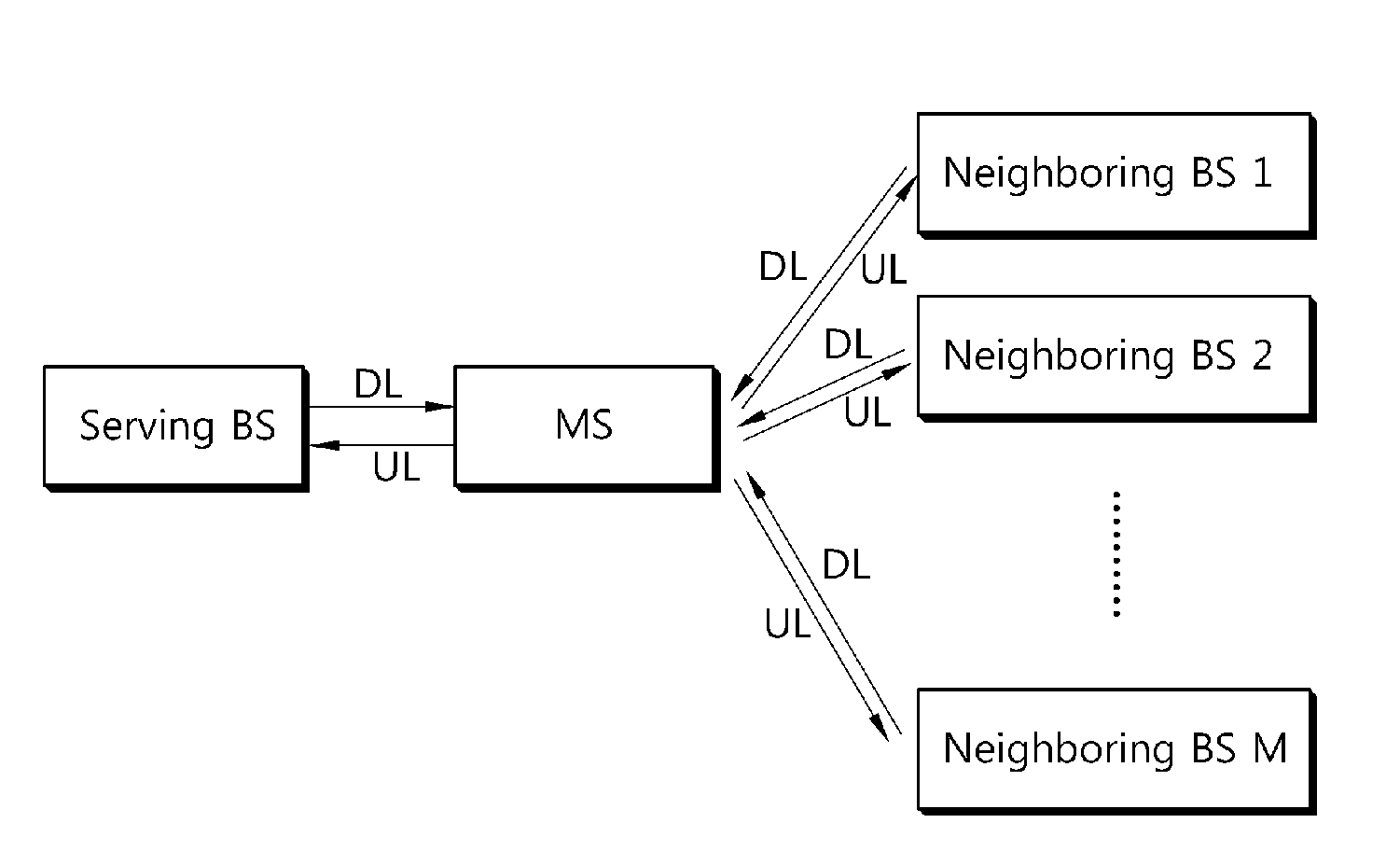
[0026]FIG. 1 is a block diagram showing an exemplary structure of a multi-cell cooperative radio communication system to which an embodiment of the present invention can be applied. Referring to FIG. 1, the multi-cell cooperative radio communication system includes a mobile station (MS), a base station (BS) located in a cell to which the MS belongs (hereinafter, such a BS is referred to as a serving BS), and neighboring BSs located in M neighboring cells (where M is an integer greater than or equal to 1). The multi-cell cooperative radio communication system can be widely deployed to provide various communication services such as voice, packet data, etc. Not only the serving BS but also the neighboring BSs parti...


PUM


Abstract

A method and apparatus of controlling uplink transmit power is provided. An estimated path-loss value for each of downlink signals from a control base station and one or more neighboring base stations is calculated. A signal path-loss value by using the calculated plurality of estimated path-loss values is obtained. An open-loop power control parameter by using the signal path-loss value is obtained. Uplink power can be controlled by considering cooperative communication of a plurality of base stations in a multi-cell cooperative radio communication system.

Description

TECHNICAL FIELD[0001]The present invention relates to radio communications, and more particularly, to a method of controlling uplink power in a radio communication system supporting co-operative communication of a plurality of relay stations, and a mobile station supporting the method.BACKGROUND ART[0002]Recently, with the generalization of information communication services, the introduction of various multimedia services, and the advent of high-quality services, a demand on radio communication services has been rapidly increased. To satisfy such a demand, various radio communication techniques are being researched in many fields. Examples thereof include various diversity schemes and a cooperative transmission scheme using neighboring base stations.[0003]The diversity scheme implies that the same data is transmitted in a repetitive and / or redundant manner to ensure reliability of communication. When the same data is transmitted through a plurality of independent paths, i.e., a div...

Claims


Application Information

Patent Timeline
Patent Type & Authority Applications(United States)
IPC IPC(8): H04W52/10
CPCH04W52/10H04W52/146H04B7/024H04W52/40H04W52/242H04W52/24
Inventor SEO, HAN BYULKIM, BYOUNG HOON
Owner LG ELECTRONICS INC
Why Eureka
Try Eureka