

Control device for controlling automatic engine stop and start
a technology of control device and automatic engine, which is applied in the direction of engine starter, machine/engine, instruments, etc., can solve the problems of not disclosing and suggesting any technique, the driver of the vehicle is uncomfortable driving, and the gear meshing noise and impact is possible, so as to achieve smooth internal restart and high accuracy
- Summary
- Abstract
- Description
- Claims
- Application Information
AI Technical Summary
Benefits of technology
Problems solved by technology
Method used
Image

Examples
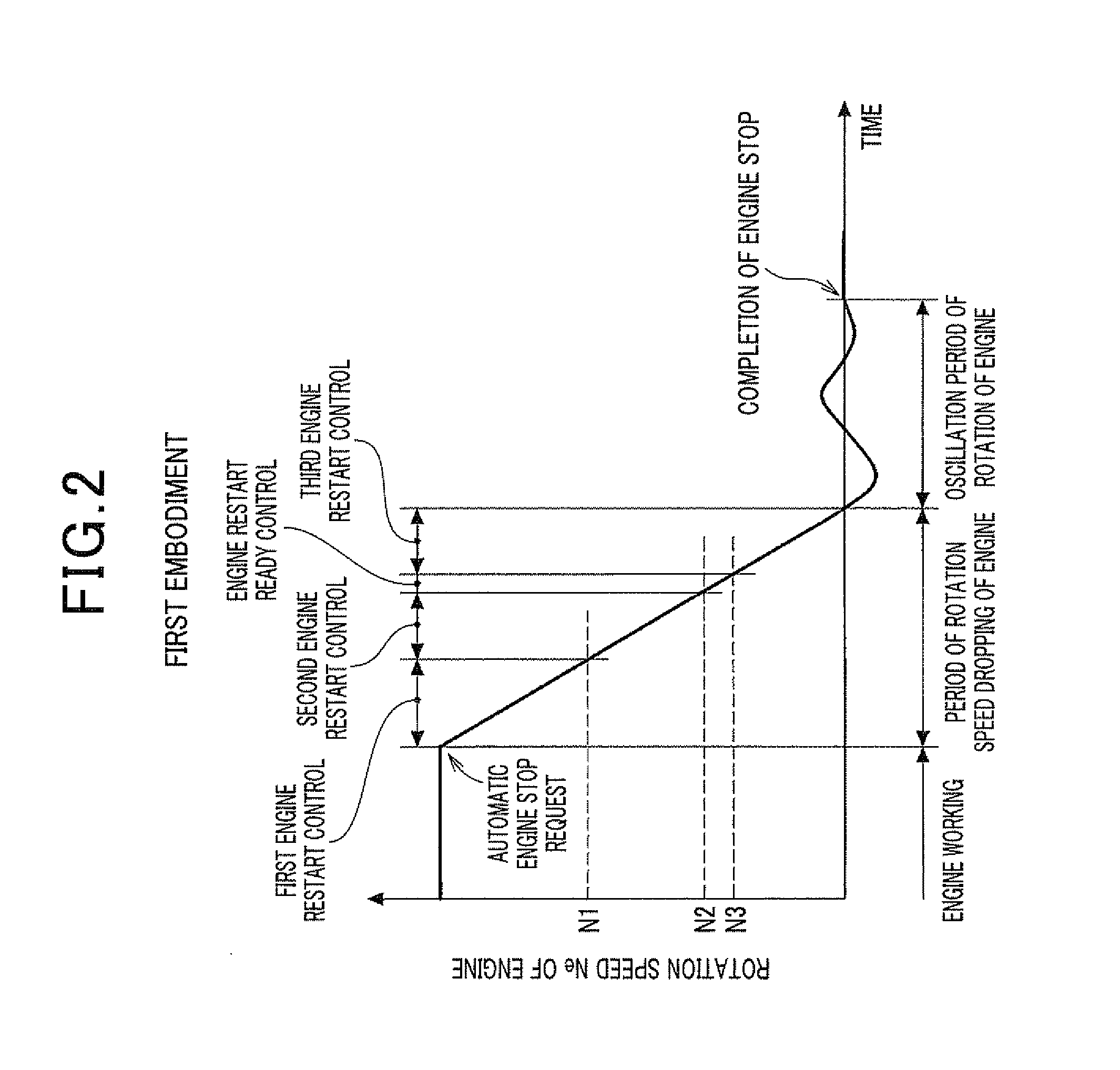
first embodiment
[0045]A description will be given of the engine control device according to a first embodiment of the present invention with reference to FIG. 1 to FIG. 6.
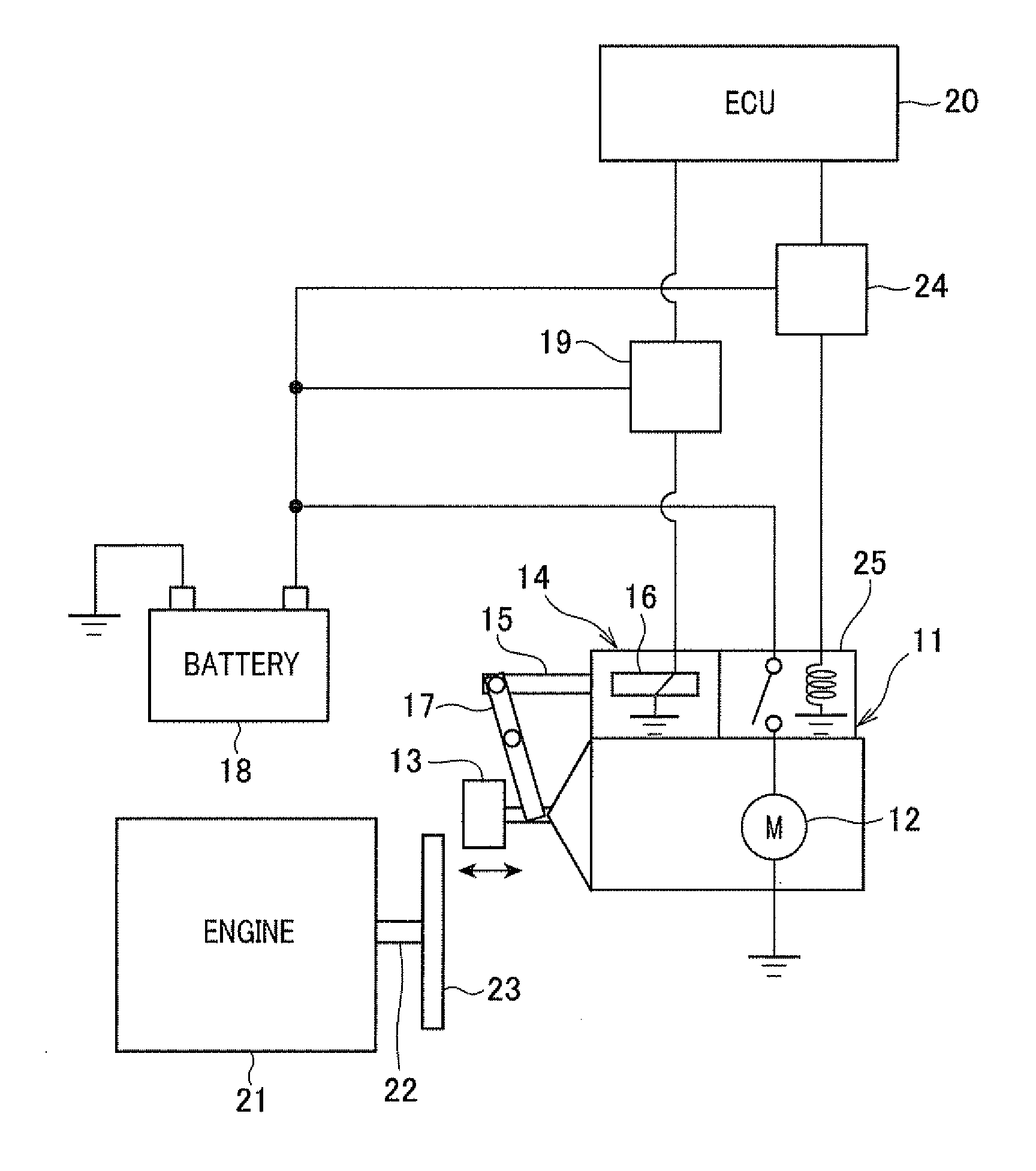
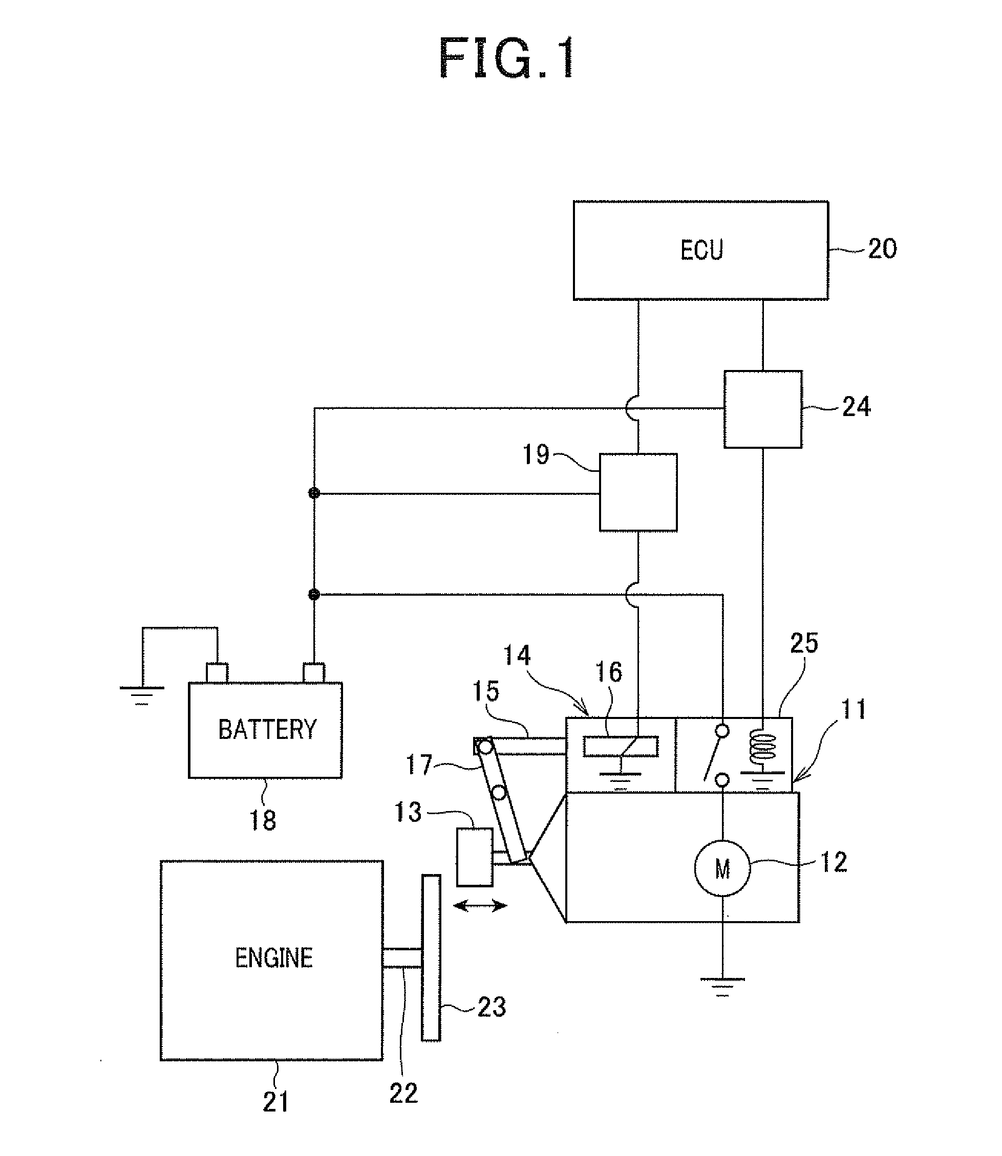
[0046]FIG. 1 is a view showing a schematic configuration of the control device 10 capable of executing an automatic engine stop and start routine according to the first embodiment of the present invention.
[0047]A description will now be given of a schematic configuration of the engine start control system with reference to FIG. 1.
[0048]A starter 11 has a mechanism for pushing the pinion gear to the ring gear when the internal combustion engine 21 is started. The ring gear is fixed to the crank shaft of the internal combustion engine 21. The starter 11 is comprised of a starter motor 12, the pinion gear 13, and an electromagnetic actuator 14. The pinion gear 13 is driven by the starter motor 12. The electromagnetic actuator 14 pushes the pinion gear 13 so as to mesh the pinion gear 13 with the ring gear 23 when the starter 11 start...
second embodiment
[0121]A description will be given of the control device according to the second embodiment of the present invention with reference to FIG. 7 and FIG. 8.
[0122]The difference between the second embodiment and the first embodiment will be explained below.
[0123]FIG. 7 is a timing chart showing the engine restart control executed by the ECU 20 in the control device according to the second embodiment of the present invention. FIG. 8 is a flow chart showing the engine restart control routine executed by the ECU 20 in the control device according to the second embodiment.
[0124]The ECU 20 executes the engine restart control routine shown in FIG. 8. The ECU 20 in the control device according to the second embodiment executes a fourth engine restart control when no engine restart request occurs and the current rotation speed Ne of the internal combustion engine 21 is decreased toward and finally reaches a fourth rotation speed N4. This fourth rotation speed N4 is a value (e.g. 100 rpm) immedia...
third embodiment
[0146]A description will be given of the control device according to the third embodiment of the present invention with reference to FIG. 10 and FIG. 11. The difference between the third embodiment and the first embodiment will be explained below.
[0147]FIG. 10 is a timing chart showing the engine restart control executed by the ECU 20 in the control device according to the third embodiment of the present invention. FIG. 11 is a flow chart showing the engine restart control routine executed by the ECU 20 in the control device according to the third embodiment.
[0148]As shown in the time chart of FIG. 10, the ECU 20 in the control device according to the third embodiment executes the engine restart ready control while the current rotation speed Ne of the internal combustion engine 21 is within the rotation speed ready range (N1≧Ne>N2) and when the engine restart request occurs while the rotation speed of the internal combustion engine is dropping due to the automatic engine stop of the...
PUM
 Abstract
Description
Claims
Application Information