Input device with dual induction coils and rotation motion output method thereof

Inactive Publication Date: 2011-07-21
KYE SYST CORP
View PDF5 Cites 15 Cited by
  • Summary
  • Abstract
  • Description
  • Claims
  • Application Information

AI Technical Summary

Benefits of technology

[0011]The present invention achieves the following efficacies. When the input device is rotated on the trace capture device, the trace capture device outputs a clockwise or anti-clockwise rotation signal to the electronic device, so as to switch the electronic device to execute a motion instruction, for example, the trace capture device outputs the clockwise or anti-clockwise rotation signal to switch a window frame of the electronic device

Problems solved by technology

However, if the mouse and the keyboard are used for controlling the computer in drawing, it is inherently inconvenient and restricted.
However, although the input manner of manipulating the pointer by using the digital pen is quite convenient, it only provides a relative displacement amount and a moving trace required by a cursor on the common window frame, such that an application scope is quite limited.
Furthermore,

Method used


Image

  • Input device with dual induction coils and rotation motion output method thereof
  • Input device with dual induction coils and rotation motion output method thereof
  • Input device with dual induction coils and rotation motion output method thereof

Examples


first embodiment

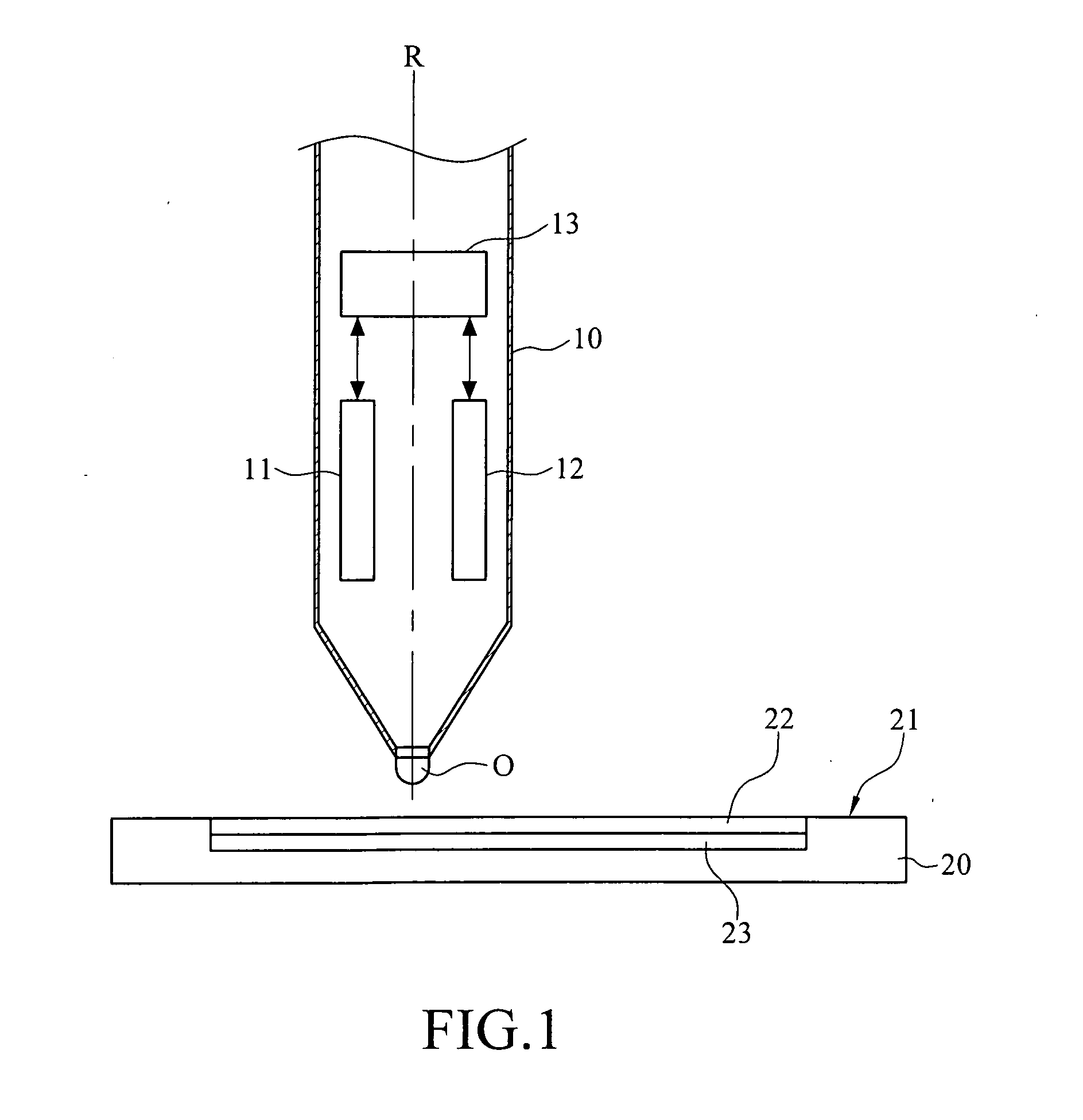
[0022]FIG. 1 is a schematic view of an input device on a trace capture device according to the present invention. Referring to FIG. 1, an input device 10 may be designed into a pen structure, but the present invention is not limited hereto. A primary coil 11 and a secondary coil 12 (it should be noted that “primary” or “secondary” is only used to differentiate the two coils, without other restrictions) are respectively disposed in the input device 10. A pen point O of the input device 10 is taken as an axle center R, and the primary coil 11 and the secondary coil 12 are respectively arranged on two opposite side edges of the axle center R side by side. In addition, the input device 10 further has an RF circuit 13, and the primary coil 11 and the secondary coil 12 are electrically connected to the RF circuit 13 respectively.

[0023]In this embodiment, the primary coil 11 generates a primary induction signal, and the secondary coil 12 generates a secondary induction signal. A primary fr...

second embodiment

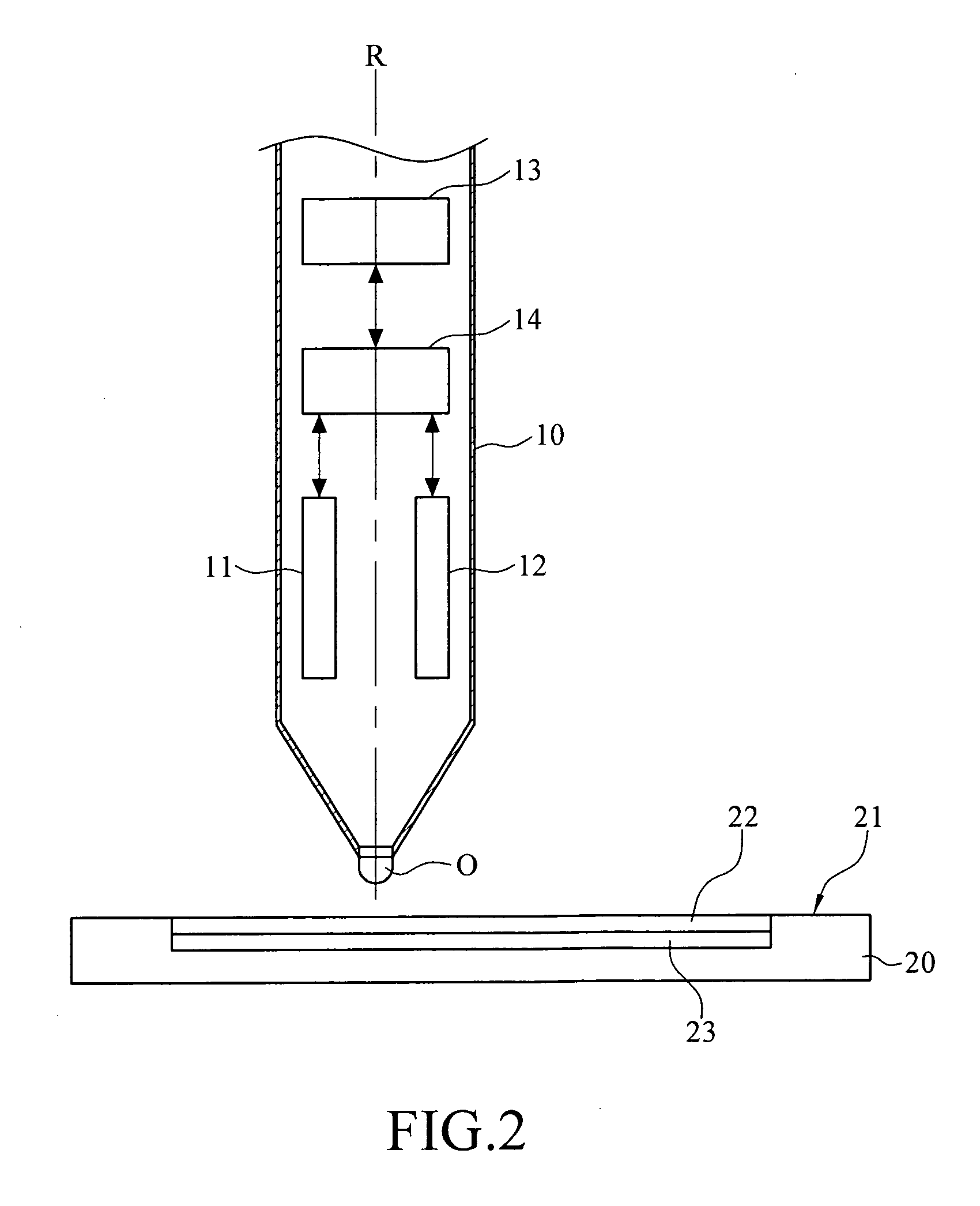
[0026]Then, the present invention is described through another embodiment. FIG. 2 is a schematic view of an input device on a trace capture device according to the present invention. The detailed implementation is approximately the same as the above embodiment, and only differences are described in the following. Referring to FIG. 2, an input device 10 further comprises a switch 14 electrically connected to a primary coil 11 and a secondary coil 12 respectively. The primary coil 11 generates a primary induction signal, the secondary coil 12 generates a secondary induction signal, and a primary frequency section of the primary induction signal is made to overlap with a secondary frequency section of the secondary induction signal.

[0027]In this embodiment, the switch 14 alternately transfers the primary induction signal or the secondary induction signal to an RF circuit 13. In brief, when the switch 14 transmits the primary induction signal, the secondary induction signal is temporari...

third embodiment

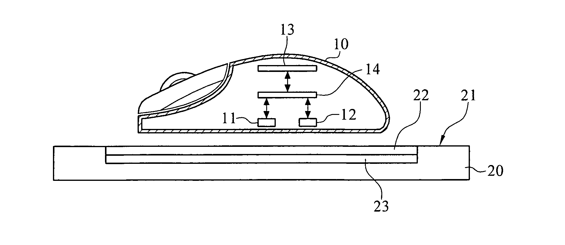
[0029]In addition, the input device 10 according to the present invention is not limited to a digital pen or other pen-shaped structures, and the input device 10 may also be designed into a mouse structure. FIG. 3 is a schematic view of an input device on a trace capture device according to the present invention. The detailed implementation is approximately the same as the above embodiment, and only differences are described in the following. Referring to FIG. 3, an input device 10 may be a mouse structure (for example, a wired mouse or wireless mouse), a primary coil 11 and a secondary coil 12 are respectively disposed within the input device 10 side by side, and the primary coil 11 and the secondary coil 12 are electrically connected to an RF circuit 13 respectively.

[0030]In this manner, the user may hold the input device 10 to move on a working area 21 of a trace capture device 20. At this time, a primary induction signal generated by the primary coil 11 is transmitted to a prima...


PUM


Abstract

An input device with dual induction coils and a rotation motion output method thereof are described, in which the input device moves on a trace capture device, such that the trace capture device outputs a trace signal to an electronic device. When the input device is rotated on the trace capture device, two coils within the input device respectively send an induction signal to the trace capture device. Then, the trace capture device respectively converts the two induction signals to two position signals, so as to determine displacement amounts and rotation directions of the two position signals, such that the trace capture device outputs a rotation signal to the electronic device, and the electronic device correspondingly executes a motion instruction according to the rotation signal.

Description

CROSS-REFERENCE TO RELATED APPLICATIONS[0001]This non-provisional application claims priority under 35 U.S.C. §119(a) on Patent Application No(s). 099101544 filed in Taiwan, R.O.C. on Jan. 20, 2010, the entire contents of which are hereby incorporated by reference.BACKGROUND OF THE INVENTION[0002]1. Field of the Invention[0003]The present invention relates to an input device with dual induction coils, and more particularly to an input device with dual induction coils and a rotation motion output method thereof.[0004]2. Related Art[0005]With the rapid progress of computer technology, a recording manner of the modern people has gradually been replaced by a manner of using the computer. Generally, the computer is controlled and operated by using a mouse and a keyboard. However, if the mouse and the keyboard are used for controlling the computer in drawing, it is inherently inconvenient and restricted. Therefore, a digital pen and a digital board have been gradually developed, such that...

Claims


Application Information

Patent Timeline
IPC IPC(8): G01B7/15G06F3/038
CPCG06F3/03544G06F3/038G06F3/03545
Inventor LIU, CHIH MIN
Owner KYE SYST CORP
Why Eureka
Try Eureka