Image recording device

Inactive Publication Date: 2014-06-12
SEIKO EPSON CORP
View PDF2 Cites 8 Cited by
  • Summary
  • Abstract
  • Description
  • Claims
  • Application Information

AI Technical Summary

Benefits of technology

[0020]Also preferably, the image recording device is further provided with an operation unit by which the worker issues a variety of commands, the third position being positioned closer to a side to which the operation unit is provided in relation to the first position and the second position. When the third position is positioned closer to the side to which the operation unit is provided in this manner, the worker more readily accesses both the operation unit and the print head that is at the third position, thus improving workability for the worker.
[0021]Also preferable is a configuration such that the image recording device is further provided with a head support section for supporting a plurality of print heads disposed along the conveyance direction, the plurality of print heads moving along with the head support section when the head support section moves. In some instances, a plurality of print heads are provided, such as where color printing is being carried out, but according to a configuration where the plurality of print heads move along with the head support section in such a case, all of the print heads can be moved at once b

Problems solved by technology

Nonetheless, the image recording devices of Patent Documents 1 and 2 have suffered problems in terms of operability when a switch is made between the maintenance state and another state (the image recording state and the manual task state).
Similarly, switching from the maintenance state to another state requires removing and considerably moving the maintenance unit in order to

Method used


Image

  • Image recording device
  • Image recording device
  • Image recording device

Examples


Example

[0024]FIG. 1 is a front view schematically illustrating a first embodiment of an image recording device as in the invention;

[0025]FIG. 2 is an enlarged front view providing a more detailed illustration of a print head periphery;

[0026]FIG. 3 is a plan view illustrating a mode of movement of a head unit in the first embodiment;

[0027]FIG. 4 is a side view illustrating a mode of movement of the head unit in the first embodiment;

Example

[0028]FIG. 5 is a front view schematically illustrating a second embodiment of an image recording device as in the invention;

[0029]FIG. 6 is a plan view illustrating a mode of movement of a head unit in the second embodiment; and

[0030]FIG. 7 is a side view illustrating a mode of movement of the head unit in the second embodiment.

DETAILED DESCRIPTION OF EXEMPLARY EMBODIMENTS

First Embodiment

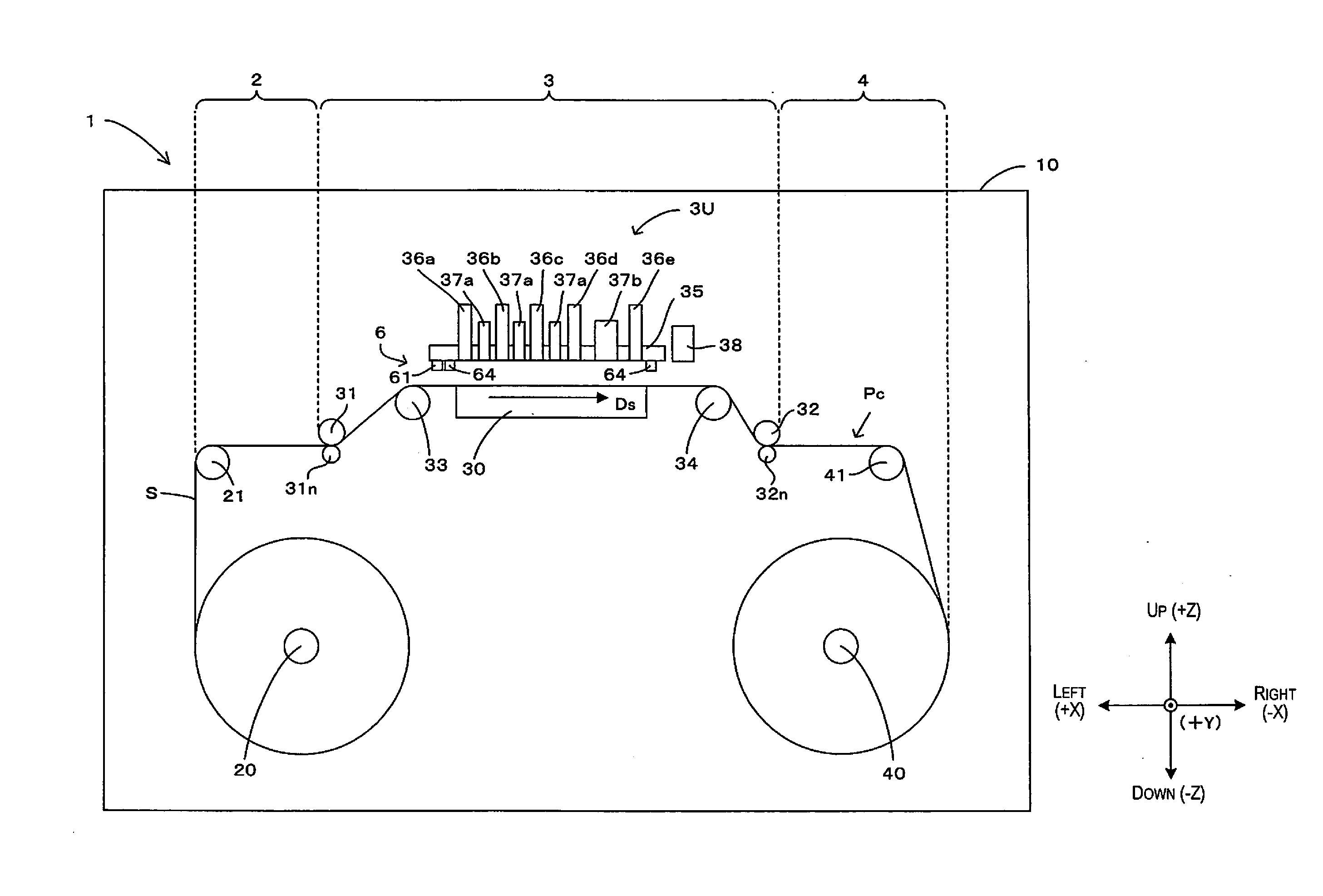
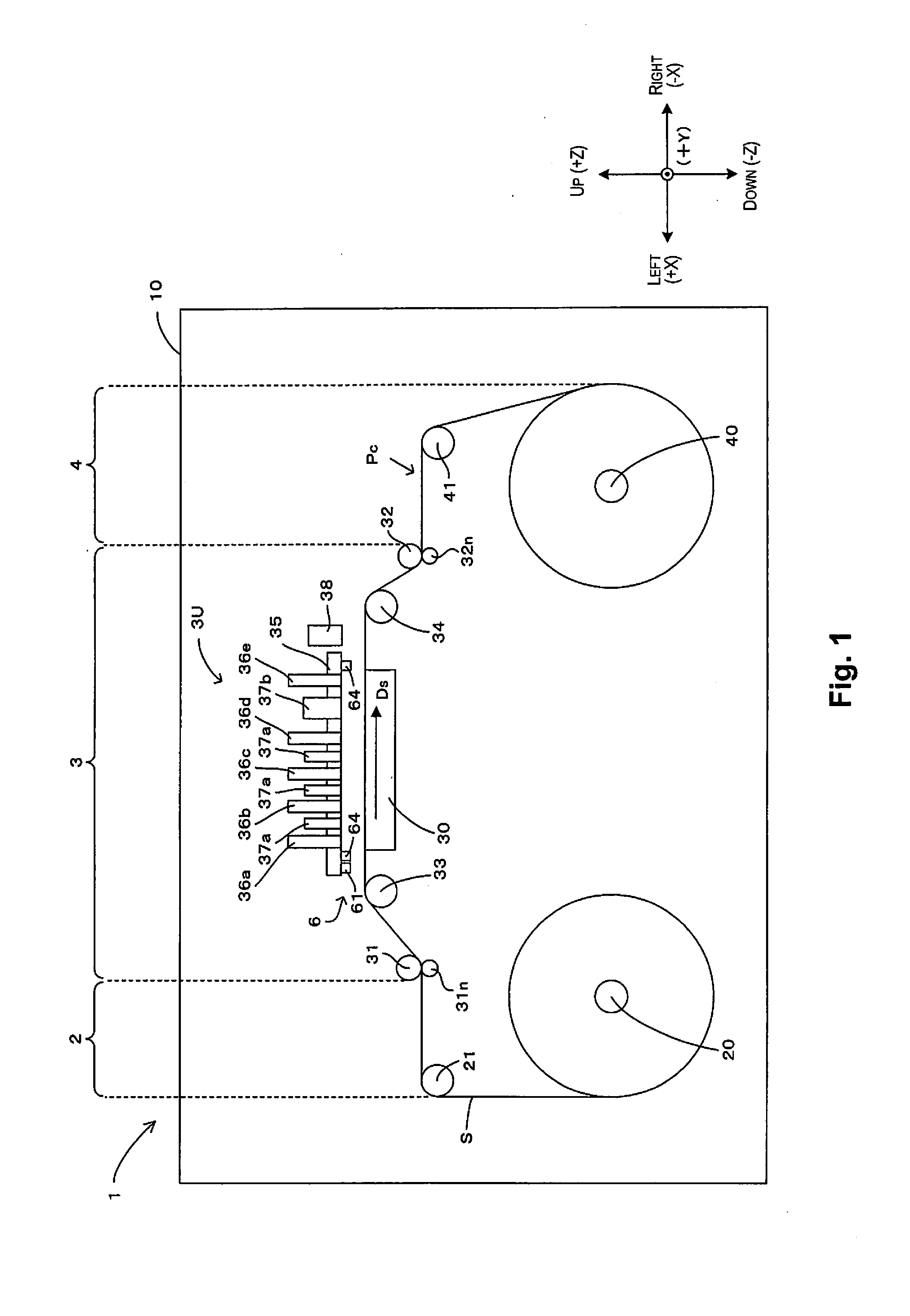
[0031]The first embodiment of the image recording device as in the invention shall be described below, with reference to the accompanying drawings. FIG. 1 is a front view schematically illustrating the first embodiment of the image recording device as in the invention. In FIG. 1 and subsequent drawings, in order to clarify the relationships of arrangement among the various sections of the device as needed, a three-dimensional coordinate system corresponding to a left-right direction X, front-rear direction Y, and vertical direction Z of an image recording device 1 shall be employed.

[0032]As illustr...


PUM


Abstract

An image recording device, wherein the image recording device is provided with a support member for supporting a recording medium, a print head for recording an image at a first position facing the support member, and a maintenance unit arranged at a position different from that of the support member in an orthogonal direction orthogonal to the direction in which the print head and the support member face each other in the first position. The image recording device is further provided with a guide mechanism for guiding movement of the print head between a first position, a second position in which the print head faces the maintenance unit, and a third position which is a different position from those of the support member and the maintenance unit in an orthogonal direction, and a space allowing for a manual task on the print head is present at the facing position of the print head at the third position.

Description

CROSS-REFERENCE TO RELATED APPLICATIONS[0001]This application claims priority to Japanese Patent Application No. 2012-270080 filed on Dec. 11, 2012. The entire disclosure of Japanese Patent Application No. 2012-270080 is hereby incorporated herein by reference.BACKGROUND[0002]1. Technical Field[0003]The present invention relates to a technique for a maintenance unit to implement maintenance or for a worker to implement a manual task on a print head for ejecting a liquid and recording an image.[0004]2. Background Technology[0005]A well-known image recording device, as with an inkjet printer, forms an image on a recording medium by ejecting a liquid from nozzles on a print head while orienting the print head to face a support member on which the recording medium is being supported. Generally, in such an image recording device, a maintenance unit can be used to implement maintenance, such as for removing a clogging of the nozzles, on the print head. In addition to maintenance by a main...

Claims


Application Information

Patent Timeline
IPC IPC(8): B41J29/00
CPCB41J29/00B41J2/16588
Inventor WANIBE, AKIHISAOKUMURA, NAOYUKI
Owner SEIKO EPSON CORP
Why Eureka
Try Eureka