Multi-Protocol Remote Control Device

Inactive Publication Date: 2007-11-08
KONINKLIJKE PHILIPS ELECTRONICS NV
View PDF7 Cites 2 Cited by
  • Summary
  • Abstract
  • Description
  • Claims
  • Application Information

AI Technical Summary

Benefits of technology

[0005] Among other things, it is an object of the invention to provide for a

Problems solved by technology

If the apparatus is not capable of two-way communication, e.g., because it is

Method used


Image

  • Multi-Protocol Remote Control Device
  • Multi-Protocol Remote Control Device
  • Multi-Protocol Remote Control Device

Examples


Embodiment Construction

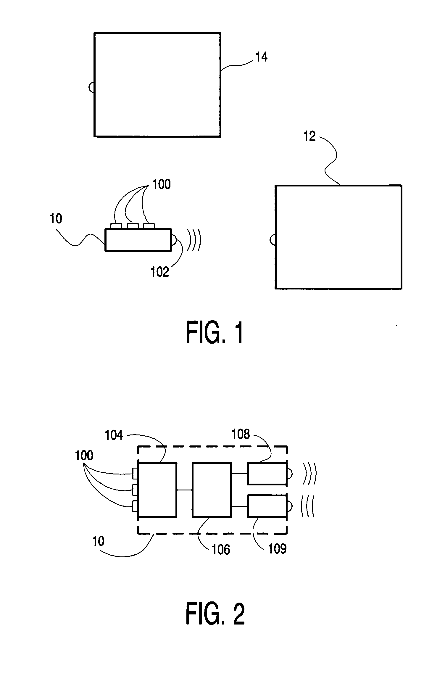
[0020]FIG. 1 is a diagram of a system, for example a home-based system with consumer electronics (CE) equipment. The system comprises first and second controllable apparatus 12 and 14, and a remote control device 10. Device 10 has a plurality of control buttons 100 and transmitter / receiver elements 102 (only one shown). Typically, transmitter / receiver elements 102 comprise an infrared source (e.g., an LED) and an infrared receiver. Other types of transmitters / receivers can be used, e.g., based on ultrasound or RF, or combinations thereof or with IR. Apparatus 12 and 14 each have a corresponding receiver, and possibly also a transmitter if the relevant one of apparatus 12 and 14 is two-way enabled. Typically, apparatus 12 and apparatus 14 are located in different rooms, or at such a distance from one another that device 10 can be used to send messages to a single one of apparatus 12 and 14 at a time. Apparatus 12 and 14 require control messages according to different protocols, e.g.,...


PUM


Abstract

A control device (10) is provided for control of an apparatus (12). The device is configured for communication with the apparatus using a one-way protocol or a two-way protocol. The device is configured to communicate a message for triggering a response from the apparatus, and to continue (31, 32; 608, 610) to communicate with the apparatus using the two-way protocol upon receipt of the response within a predetermined time interval, and to continue (33, 34, 35; 602, 604) to communicate with the apparatus using the one-way protocol in the absence of the response within the time interval.

Description

FIELD OF THE INVENTION [0001] The invention relates to a control device for controlling equipment, e.g., consumer electronics (CE) equipment, preferably through wireless communication using, e.g., infrared (IR) or radio frequency (RF). The invention further relates to control software for installing on such as control device. BACKGROUND ART [0002] Control of an apparatus through a remote control device requires an agreed control protocol that controls the generation and interpretation of control message signals by the remote control device and the apparatus, respectively. The protocol defines the relationship between commands and signal characteristics. In principle, this relationship can be chosen arbitrarily, as long as the remote control device and the apparatus comply with the same relationship. Accordingly, many different protocols exist. These include two-way protocols, in which the apparatus returns a response to the remote control device in reply to receiving a command from ...

Claims


Application Information

Patent Timeline
IPC IPC(8): H04J3/16G08C19/28
CPCG08C19/28G08C2201/92G08C2201/20
Inventor GRIEP, PIETER DINGENIS
Owner KONINKLIJKE PHILIPS ELECTRONICS NV
Why Eureka
Try Eureka