Camera module with lens array

a camera module and lens array technology, applied in the field of camera modules, can solve the problem that the thickness of the camera module tends to increase in the optical axis direction

Inactive Publication Date: 2011-07-21
HON HAI PRECISION IND CO LTD
View PDF5 Cites 178 Cited by
  • Summary
  • Abstract
  • Description
  • Claims
  • Application Information

AI Technical Summary

Problems solved by technology

However, as the depth of field increases, a lens system is required to consist of more lenses, and therefore the thickness of the camera module tends to increase in the optical axis direction.

Method used


Image

  • Camera module with lens array
  • Camera module with lens array
  • Camera module with lens array

Examples


Embodiment Construction

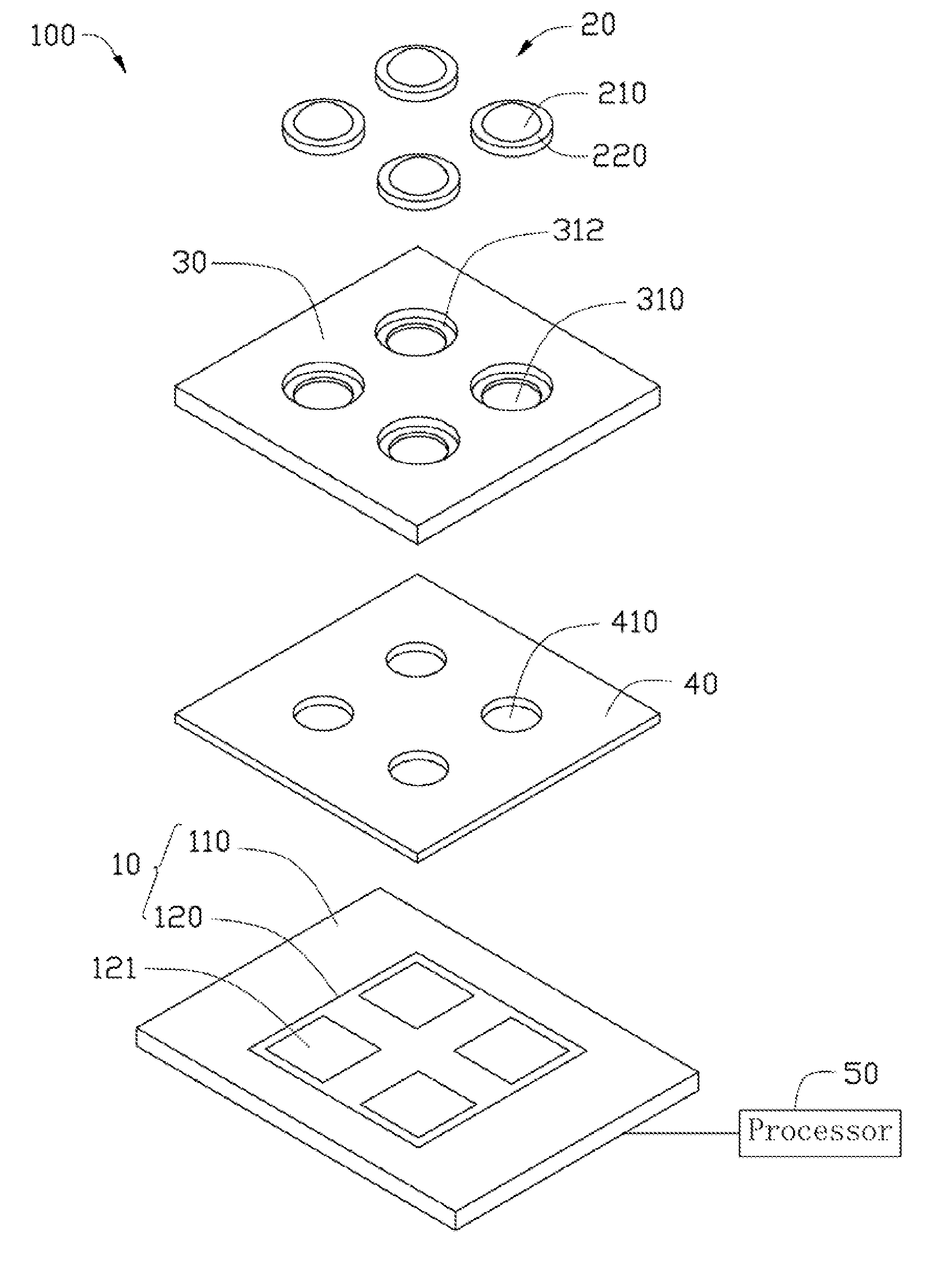
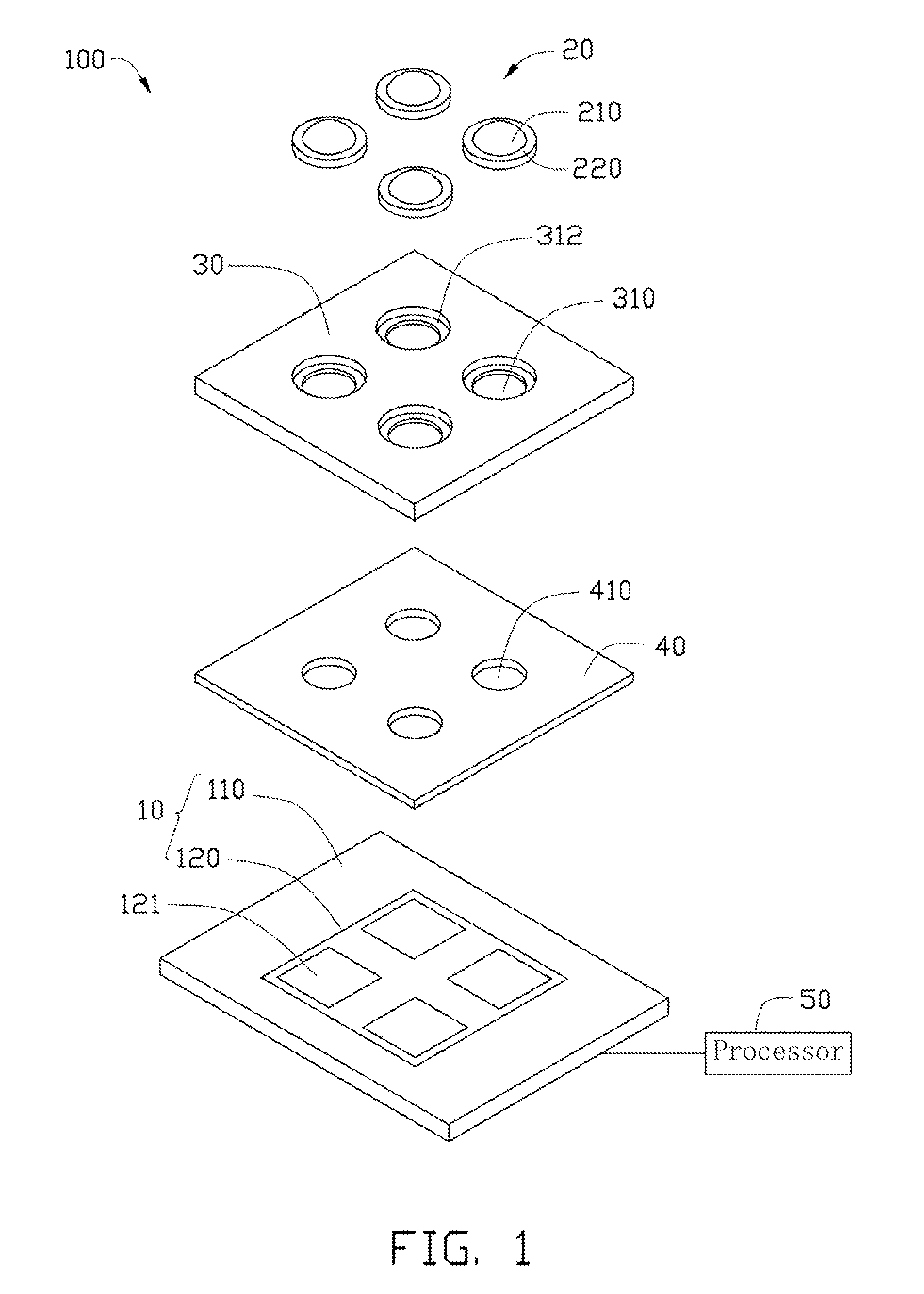
[0008]Referring to FIG. 1, a camera module 100, according to a first exemplary embodiment, includes an image sensor 10, four lenses 20, a supporting plate 30, a spacer 40, and a processor 50. In this embodiment, the four lenses 20 are arranged in a rectangular array on a common plane.

[0009]The image sensor 10 is selected from the group consisting of a complementary metal oxide semiconductor (CMOS) image sensor and a charge coupled device (CCD) image sensor. The image sensor 10 includes a base 110 and a sensing area / region 120 in the center of the base 110 (i.e., centered upon the base 110). The sensing area / region 120 includes a plurality of sensing portions 121. In this embodiment, there are four sensing portions 121, and the four sensing portions 121 are arranged in a rectangular array corresponding to the lenses 20.

[0010]Each lens 20 may be made of glass or resin and can be an aspherical lens or a spherical lens for example. The lenses 20 have at least two different focal lengths...


PUM


Abstract

A camera module includes a plurality of lenses with different focal lengths, a supporting plate, an image sensor, and a processor. The supporting plate defines a plurality of through holes receiving the corresponding lenses. The image sensor includes a sensing area. The sensing area is configured for receiving light through the lenses and the through holes and converting the light into electrical signals. The processor is electrically connected to the image sensor. The processor is configured for processing the electrical signals to form sub-images of a same view of same objects with different depths of field and then combining the sub-images into a final image.

Description

BACKGROUND[0001]1. Technical Field[0002]The present disclosure relates to imaging technology and, particularly, to a camera module.[0003]2. Description of Related Art[0004]Nowadays, camera modules for forming an image of a subject on a solid-state imaging device via a lens system are used widely for digital still cameras and mobile phone cameras. In recent years, it has been required for camera modules to have a larger depth of field in combination with a lower profile. However, as the depth of field increases, a lens system is required to consist of more lenses, and therefore the thickness of the camera module tends to increase in the optical axis direction.[0005]Therefore, it is desirable to provide a camera module, which can overcome or at least alleviate the above-mentioned problems.BRIEF DESCRIPTION OF THE DRAWINGS[0006]FIG. 1 is an exploded view of a camera module, according to a first exemplary embodiment.[0007]FIG. 2 is an exploded view of a camera module, according to a sec...

Claims


Application Information

Patent Timeline
Patent Type & Authority Applications(United States)
IPC IPC(8): H04N5/228
CPCH04N5/2257G03B17/12H04N23/57H04N25/41
Inventor CHANG, JEN-TSORNG
Owner HON HAI PRECISION IND CO LTD
Why Eureka
Try Eureka