Pneumatic tire

a pneumatic tire and tire body technology, applied in the field of pneumatic tires, can solve the problems of easy deterioration of the traction pattern and low tire rolling resistance, and achieve the effects of maintaining the snow traction performance and tire rolling resistance, increasing the rigidity of the land portion, and reducing the tire rolling resistan

Active Publication Date: 2011-07-28
THE YOKOHAMA RUBBER CO LTD
View PDF9 Cites 4 Cited by
  • Summary
  • Abstract
  • Description
  • Claims
  • Application Information

AI Technical Summary

Benefits of technology

[0026]In the pneumatic tire according to the invention, because a ratio G=(A+B) / X of the sum A+B of the groove area A of the circumferential direction main grooves and the groove area B of the width direction grooves to the contact area X of the tread portion is set to a predetermined value or smaller (G≦0.25), the rigidity of the land portions increases. This prevents the land portions from deforming when the tire contacts with the ground, which advantageously reduces the rolling resistance of the tire. The ratio S=B / (A+B) of the groove area B of the width direction grooves and the sum A+B of the groove area A of the circumferential direction main grooves and the groove area B of the width direction grooves is set appropriately. This advantageously maintains the snow traction performance and the rolling resistance of the tire. The ratio Gs of the groove area C of the tread shoulder areas to the contact area Y of the tread shoulder areas is set appropriately. This advantageously improves the uneven-wear resistance of the tire.

Problems solved by technology

However, the traction pattern easily deteriorates the low rolling resistance of the tire.

Method used


Image

  • Pneumatic tire
  • Pneumatic tire
  • Pneumatic tire

Examples


embodiment

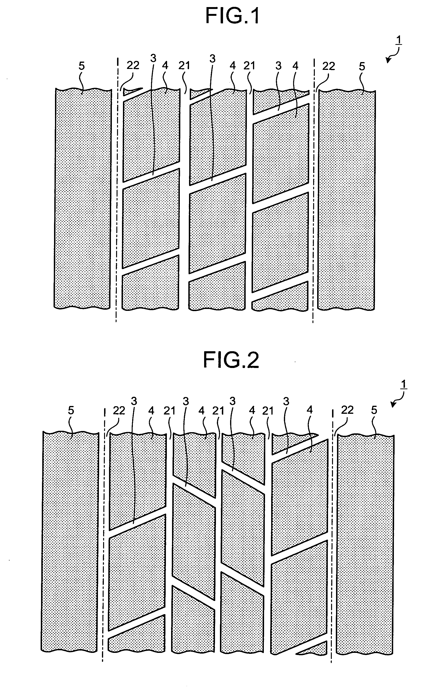
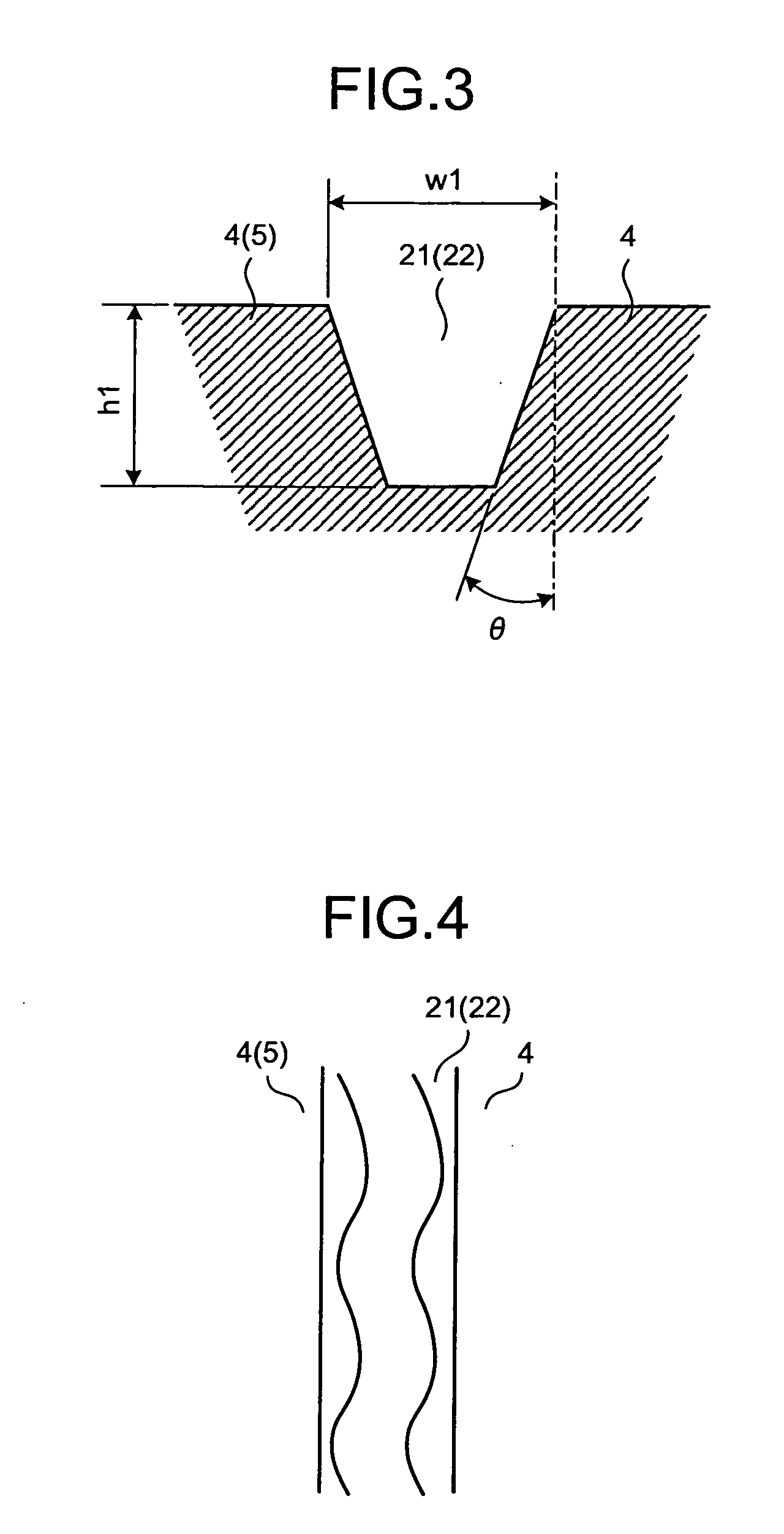
[0041]FIG. 1 is a top view of a tread of a pneumatic tire according to an embodiment of the present invention. FIGS. 2 to 6 are explanatory views of modifications of the pneumatic tire shown in FIG. 1. FIG. 7 is a table of results of performance tests of pneumatic tires according to the embodiment of the present invention.

[0042]In a pneumatic tire 1, a traction pattern is formed in a tread portion by three or more circumferential direction main grooves 21, 22 that extend in a tire circumferential direction; a plurality of width direction grooves 3 that extend in a tire width direction; and a plurality of lines of land portions 4, 5 that are sectioned by the circumferential direction main grooves 21, 22 and the width direction grooves 3. At centerlines 1 of the circumferential direction main grooves 22 on the outermost sides in the tire width direction, which serve as borders, the tread portion is sectioned into a center area and tread shoulder areas. The tread shoulder areas are the...


PUM


Abstract

A pneumatic tire includes a tread portion; three or more circumferential direction grooves; width direction grooves; and lines of land portions. When a tread center area and tread shoulder areas are sectioned at centerlines of the circumferential direction grooves in outermost sides in the tire width direction, a ratio G=(A+B)/X of a sum A+B of a groove area A of the circumferential direction grooves and a groove area B of the width direction grooves to a contact area X of the tread portion is in a range of G≦0.25, a ratio S=B/(A+B) of the groove area B to the sum A+B is in a range of 0.25<S<0.45, a ratio Gs=C/Y of a groove area C of the tread shoulder areas to a contact area Y of the tread shoulder areas is in a range of Gs<0.20, and the ratio G and the ratio Gs have a relation of Gs<G.

Description

TECHNICAL FIELD[0001]The present invention relates to a pneumatic tire. More specifically, the present invention relates to a pneumatic tire whose rolling resistance can be reduced while the snow traction performance of the tire is maintained.BACKGROUND ART[0002]In a pneumatic tire that has a traction pattern, width direction grooves are arranged in a tread center area and tread shoulder areas to ensure the snow traction performance. However, the traction pattern easily deteriorates the low rolling resistance of the tire. The above configuration has an objective to improve the low rolling resistance while the snow traction performance of the tire is maintained.[0003]As a conventional pneumatic tire with the above objective, the technology disclosed in Patent Document 1 is known. In the conventional pneumatic tire (heavy load radial tire), four longitudinal main grooves that continuously extend in a circumferential direction and have a groove width not less than 3.0 mm and not more t...

Claims


Application Information

Patent Timeline
Patent Type & Authority Applications(United States)
IPC IPC(8): B60C11/03
CPCB60C11/00B60C11/0306B60C2011/0025B60C2200/06B60C11/033B60C11/0309Y02T10/86
Inventor NAKANO, TOMOYA
Owner THE YOKOHAMA RUBBER CO LTD
Why Eureka
Try Eureka