Boundary Microphone

Inactive Publication Date: 2011-07-28
AUDIO-TECHNICA
View PDF7 Cites 10 Cited by
  • Summary
  • Abstract
  • Description
  • Claims
  • Application Information

AI Technical Summary

Benefits of technology

[0006]An object of the present invention is to provide a boundary microphone including a pressure-sensitive switch that exhibits enhanced feeling of pressing operation by an operator, is operable with small pressing force by the operator, and does not break during the operation.
[0007]Another object of the present invention is to provide a boundary microphone including a pressure-sensitive switch having an enhanced contact pressure per unit area and thus having high reliability of operation.
[0008]A boundary microphone of the present invention includes a base; a microphone unit mounted on the base, the microphone unit converting sound into electrical signals; a pressure-sensitive switch of a membrane type switching on/off output signals from the microphone unit; the pressure-sensitive switch comprising a circuit board; a membrane covering the circuit board; an electrode pattern provided on the circuit board, the electrode pattern turning on

Problems solved by technology

Use of a push switch having click feeling generates noise due to vibration of the microphone itself by the switching operation with click feeling.
A disadvantage of the membrane pressure-sensitive switch 1 is a small stroke of the thin membrane 20 when the operator presses the pressure-sensitive switch 1 by his/her finger 21; hence, the operator does not feel perceptible displacement a

Method used


Image

  • Boundary Microphone
  • Boundary Microphone
  • Boundary Microphone

Examples


Embodiment Construction

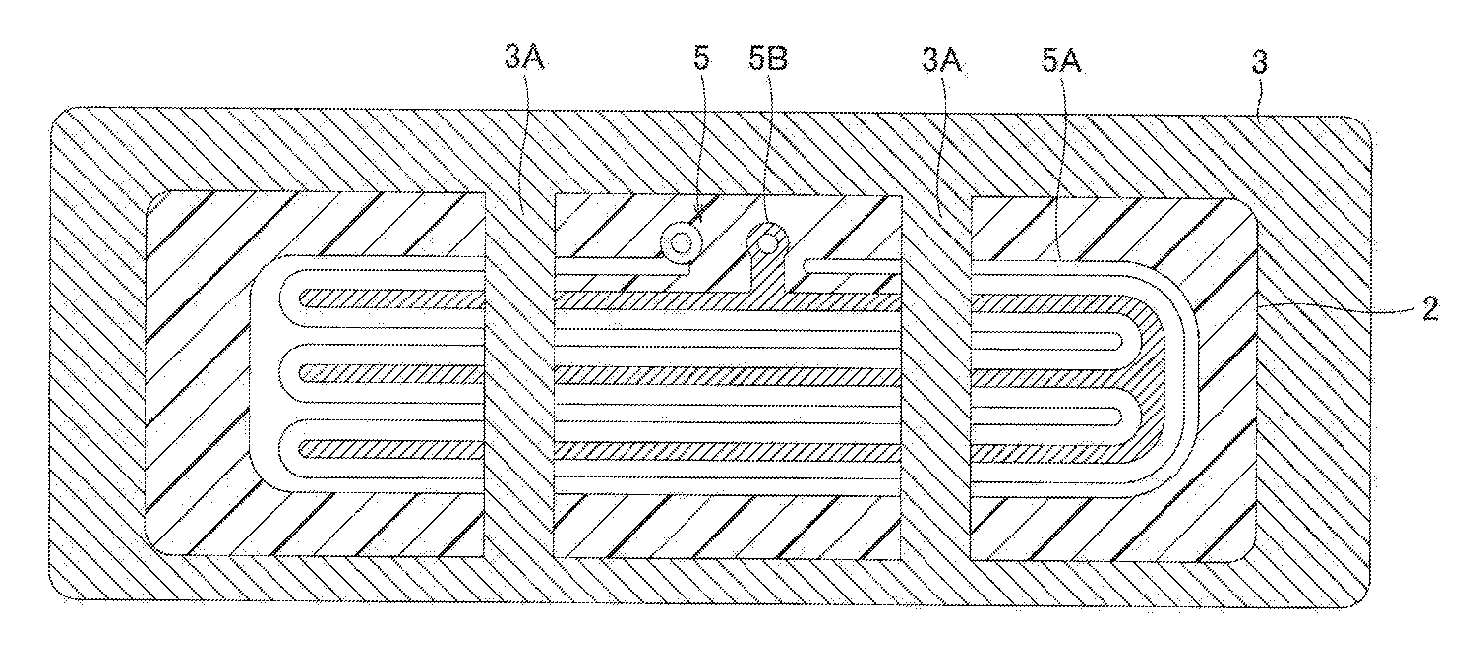
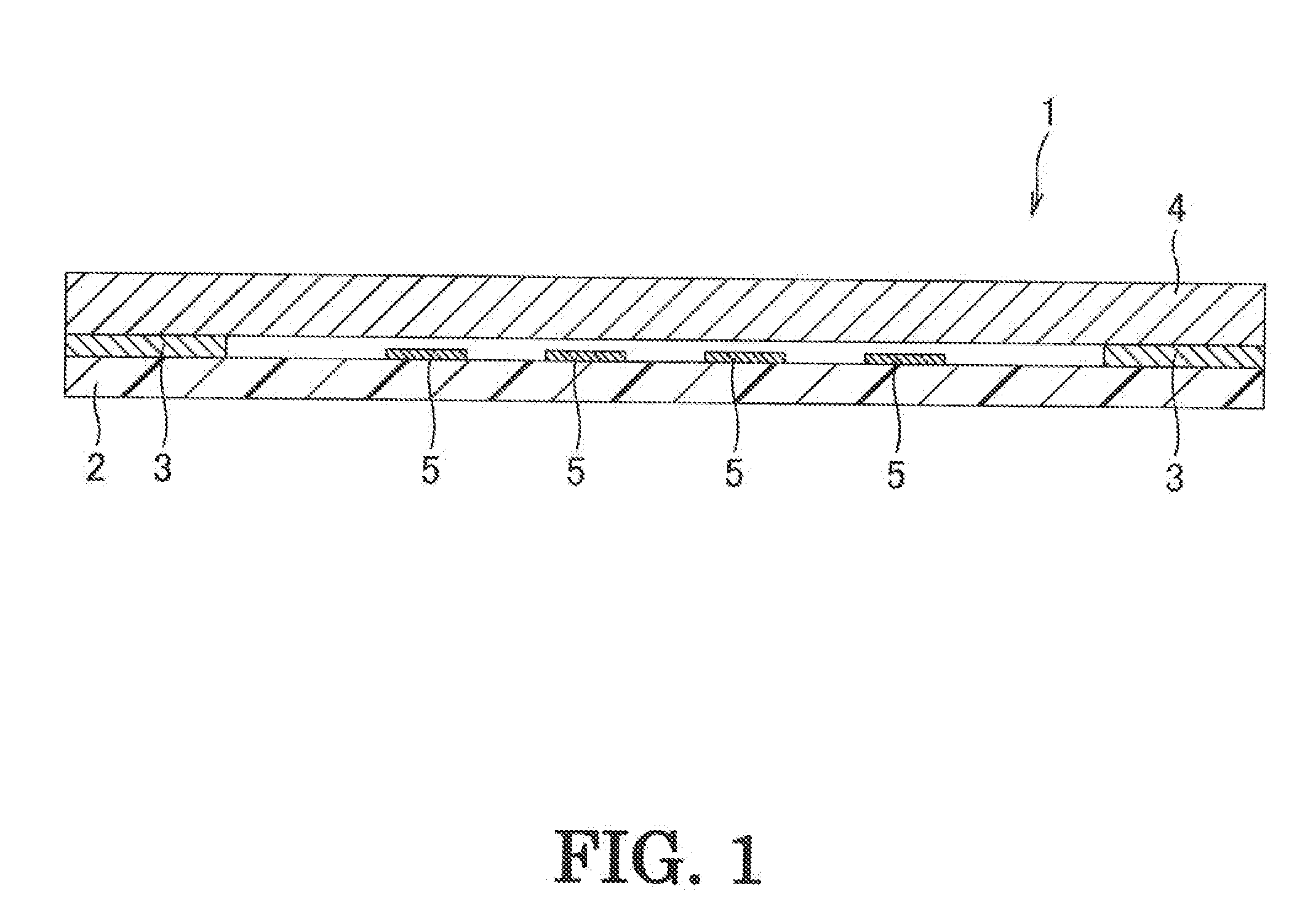
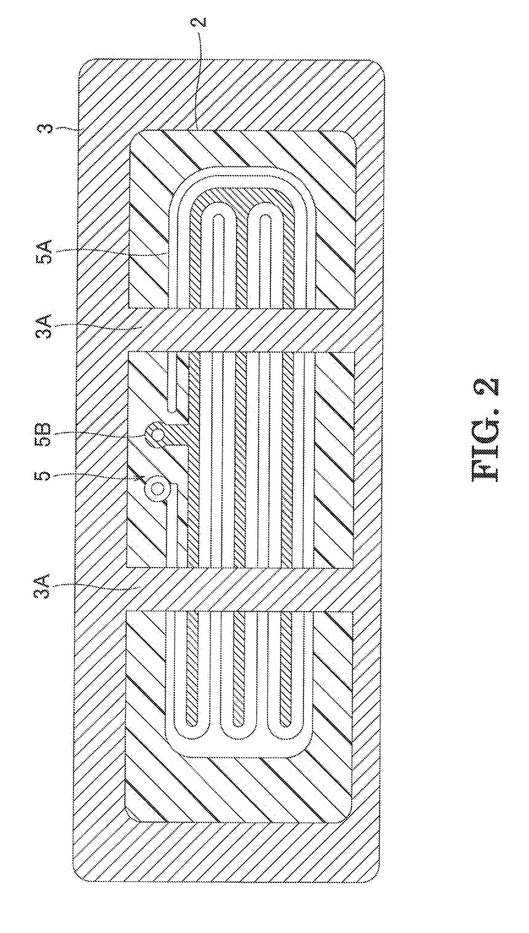
[0015]Embodiments of a boundary microphone in accordance with the present invention are described below with reference to the attached drawings. The present invention is characterized by a configuration of a pressure-sensitive switch of the boundary microphone and the configuration of the main frame of the boundary microphone can be the same as that of the conventional microphone shown in FIG. 5. Accordingly, the configuration of the main frame of the boundary microphone of the present invention is described with reference to FIG. 5.

[0016]The boundary microphone 11 primarily includes a flat metal base 10 having an opening on the top, a microphone cover 15 that is composed of a metal plate having a large number of openings (sound inlet openings) and covers the top surface of the base 10, a pressure-sensitive switch 1, an external thread 12, a circuit board 18 of the boundary microphone 11, and a microphone unit 13. A microphone cord 16 and a cord bush 17 are disposed at the rear of t...


PUM


Abstract

A boundary microphone includes a base, a microphone unit that is mounted on the base and converts sound into electrical signals, and a pressure-sensitive switch that switches on/off the output signals from the microphone unit. The pressure-sensitive switch includes a membrane covering a circuit board having an electrode pattern on its upper surface, a spacer disposed between the membrane and the circuit board. The electrode pattern is turned on the pressure-sensitive switch upon contact with the membrane. The membrane is composed of a conductive cloth having flexibility in the thickness direction.

Description

TECHNICAL FIELD[0001]The present invention relates to a boundary microphone that has a pressure-sensitive switch switching output signals from a microphone unit and is primarily used on a table.Background Art[0002]Boundary microphones have pressure-sensitive switches switching output signals from microphone units and are used on tables. The boundary microphones, which are primarily used on desks or floors in, for example, TV studios and conference halls, are also called surface mount microphones (on-surface sound pickup microphones). For example, as is disclosed in Japanese Unexamined Patent Application Publication No. 2008-288933, a boundary microphone is primarily used on a table; thus, a microphone unit and an accompanying circuit are incorporated into a low-profile flat casing in many cases so that its existence is unnoticed.[0003]With reference to FIG. 5, a boundary microphone 11 includes a flat metal base 10 having an opening on the top, a microphone cover 15 that is composed ...

Claims


Application Information

Patent Timeline
IPC IPC(8): H04R11/04
CPCH04R1/083
Inventor AKINO, HIROSHI
Owner AUDIO-TECHNICA
Why Eureka
Try Eureka