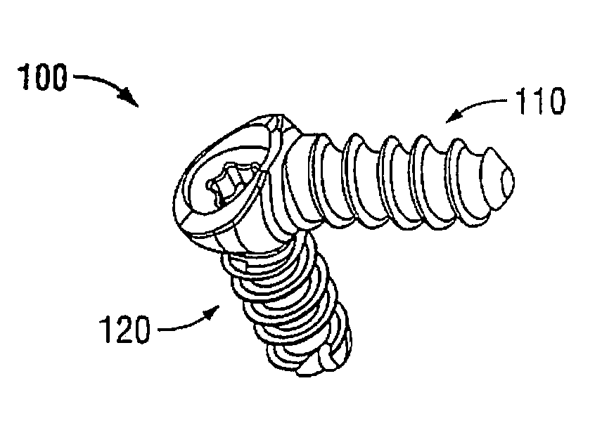
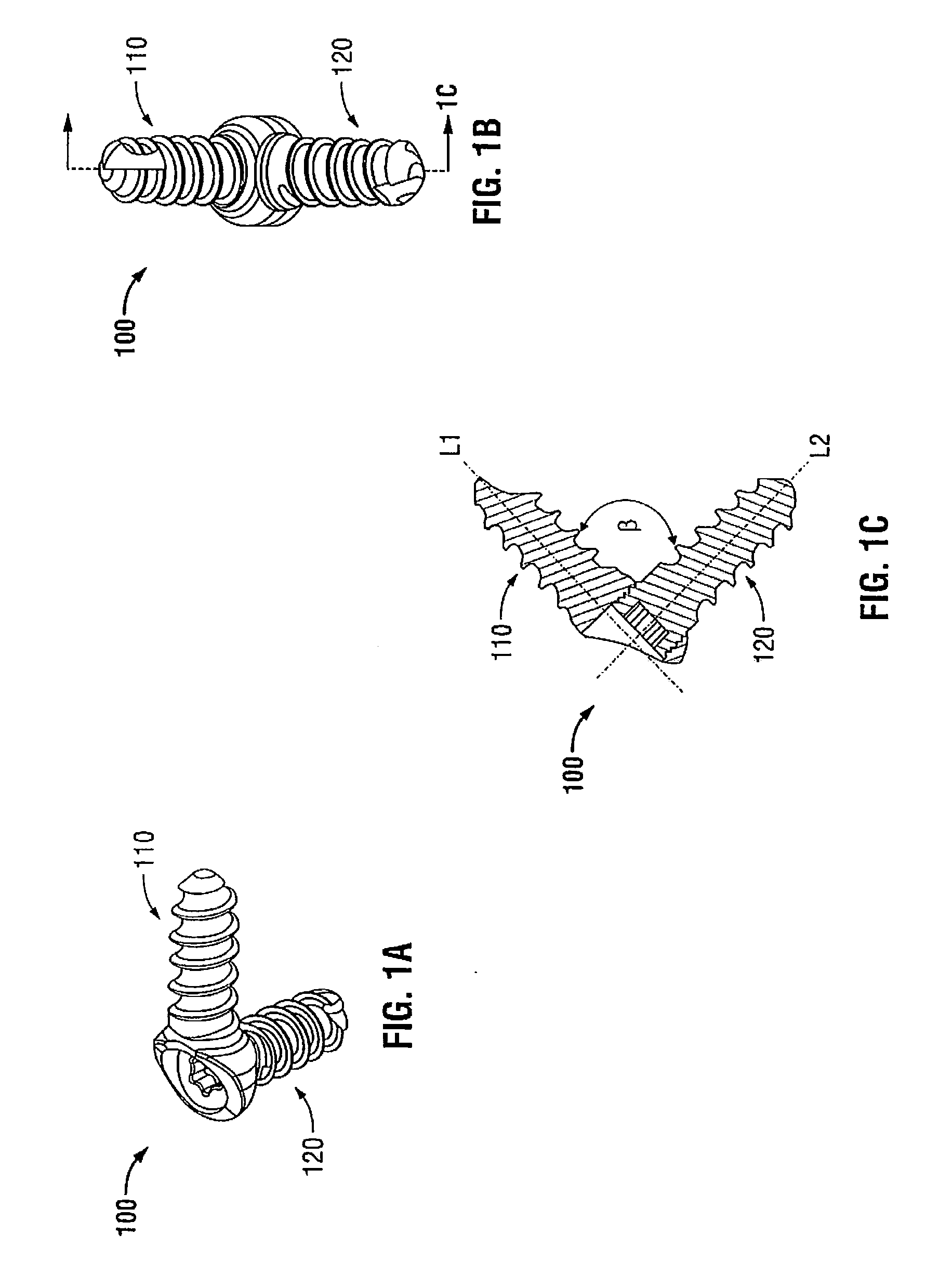
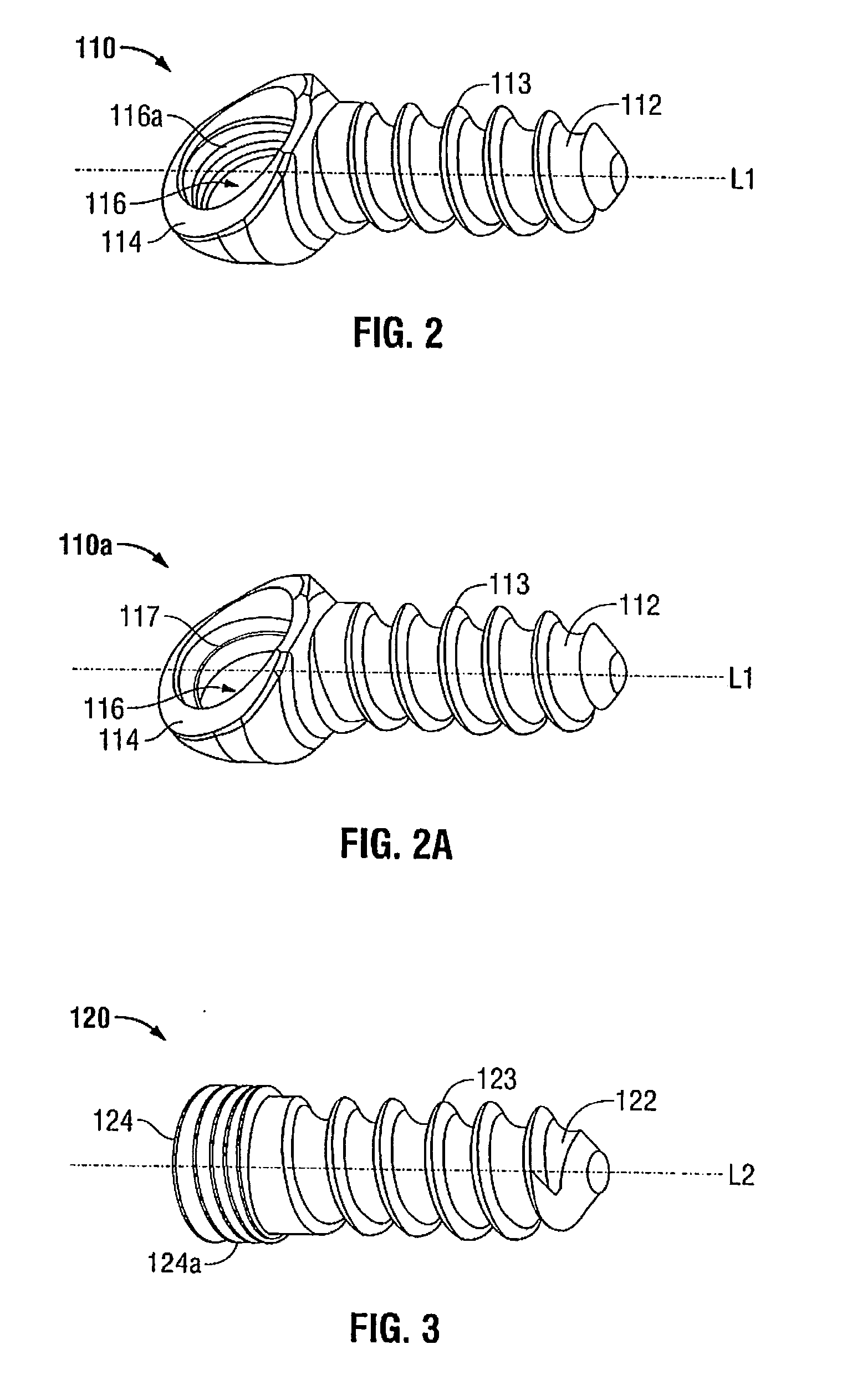
Bone screw assembly

a bone screw and assembly technology, applied in the field of orthopedic surgery, can solve the problems of less effective resistance to rotational and distraction (extension) forces, less stability afforded by them, and significant risk of spinal neural elements and other spinal structures, etc., to eliminate the need for additional posterior fixation

Inactive Publication Date: 2011-07-28
GOREK JOSEF
View PDF22 Cites 77 Cited by
  • Summary
  • Abstract
  • Description
  • Claims
  • Application Information

AI Technical Summary

Problems solved by technology

Posterior pedicle screw fixation can achieve this stability but also includes significant risk of injury to the spinal neural elements and damage to other spinal structures such as muscle, ligaments, facet joints etc.
These devices can effectively resist compressive forces, bending forces and translational forces (shear), but are less effective in resisting rotational and distraction (extension) forces.
Another concern related to these anterior adjunctive fixation devices is that the stability afforded by them is not always sufficient to eliminate the need for additional posterior fixation.
Factors that limit the strength of the fixation include fixation at the bone screw interface.
For instance, when the interrelationship of the plate to the screws is not in a “locked” relationship, the strength of the bony fixation is compromised.
A limited number of screws also can adversely affect fixation.

Method used


Image

  • Bone screw assembly
  • Bone screw assembly
  • Bone screw assembly

Examples


Embodiment Construction

[0037]Particular embodiments of the present disclosure will be described herein with reference to the accompanying drawings. As shown in the drawings and as described throughout the following description, and as is traditional when referring to relative positioning on an object, the terms “proximal” and “trailing” may be employed interchangeably, and should be understood as referring to the portion of a structure that is closer to a clinician during proper use. The terms “distal” and “leading” may also be employed interchangeably, and should be understood as referring to the portion of a structure that is farther from the clinician during proper use. In addition, the term “cephalad” is used in this application to indicate a direction toward a patient's head, whereas the term “caudad” indicates a direction toward the patient's feet. Further still, the term “medial” indicates a direction toward the middle of the body of the patient, whilst the term “lateral” indicates a direction towa...


PUM


Abstract

A bone screw assembly includes a first bone screw, second bone screw, and a coupler. The first bone screw defines a first axis and the second bone screw defines a second axis. The coupler is operably associated with the first bone screw and the second bone screw. The coupler is adapted to mount the first bone screw and the second bone screw to adjacent bone structures. The first axis of the first bone screw and the second axis of the second bone screw define an angle therebetween. The first bone screw and the second bone screw are securable to each other.

Description

CROSS REFERENCE TO RELATED APPLICATIONS[0001]This application claims priority to, and the benefit of, U.S. Provisional Patent Application Ser. No. 61 / 188,173 filed Aug. 7, 2008, the entire contents of which are incorporated by reference herein.BACKGROUND[0002]1. Technical Field[0003]The present disclosure relates generally to orthopedic surgery with particular regard to spinal surgery. Specifically, the present disclosure relates to an apparatus and methods for fixating adjacent vertebral bodies relative to each other using bone screws.[0004]2. Description of Related Art[0005]There has been considerable interest and development in the field of spinal surgery to achieve spinal fusion, specifically in anterior column surgery. In the lumbar spine, for instance, there is now great interest in minimizing the morbidity associated with fusion procedures, i.e., the muscle stripping, denervation and / or devascularization that often accompany the more commonly utilized posterior approach fusio...

Claims


Application Information

Patent Timeline
IPC IPC(8): A61B17/88A61B17/86
CPCA61B17/7011A61B17/7032A61B17/8605A61B17/7064A61B17/7067A61B17/7059
Inventor GOREK, JOSEFJONES, SCOTT
Owner GOREK JOSEF
Why Eureka
Try Eureka