Method and Apparatus for the Realization of a Failsafe Time Function

a failsafe time and function technology, applied in the direction of instruments, generating/distributing signals, computing, etc., can solve the problem that the timer monitoring function, however, does not provide an acceptable level of reliability

Active Publication Date: 2011-07-28
SIEMENS AG
View PDF5 Cites 7 Cited by
  • Summary
  • Abstract
  • Description
  • Claims
  • Application Information

AI Technical Summary

Benefits of technology

[0008]It is therefore an object of the invention to provide a method which enables an oscillating crystal that is available in the system to be used for the explicit generation of a time function, and to provide an apparatus that does not have the above-described disadvantages and that operates without additional hardware (HW) components.
[0011]It is advantageous if the clock rate of the periodic interrupt signal is increased and the additional interrupt signals are filtered out. The previous processing routine thus advantageously obtains as many interrupt signals as before. The inventive method can thus be used on a standard operating system.

Problems solved by technology

This timer monitoring function, however, does not provide an acceptable level of reliability, i.e., the function fails to meet the requirements set forth in the corresponding standards, e.g., International Electrotechnical Commission Standard (IEC) 61508.

Method used


Image

  • Method and Apparatus for the Realization of a Failsafe Time Function
  • Method and Apparatus for the Realization of a Failsafe Time Function
  • Method and Apparatus for the Realization of a Failsafe Time Function

Examples


Embodiment Construction

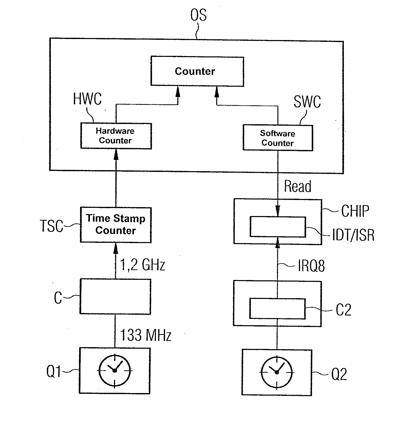
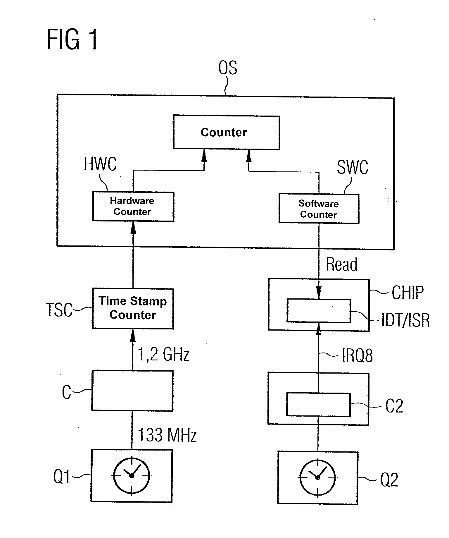
[0023]FIG. 1 shows a schematic block diagram of the process flow in accordance with the invention, where two time signals are illustrated that are generated by crystals Q1 and Q2 as shown in the hardware configuration of a central processor unit of FIG. 2. Returning to FIG. 1, the left crystal Q1 typically generates a frequency of 14.31818 MHz, where the signal is also forwarded to a phase-locked loop (PLL), such as an Intel Core with a 1.2 GHz clock rate. The time stamp counter (TSC) operates with the processor clock, where an overflow can typically be expected here after 487 years. This standard hardware counter (HWC) is then read out and standardized to 1 ms.

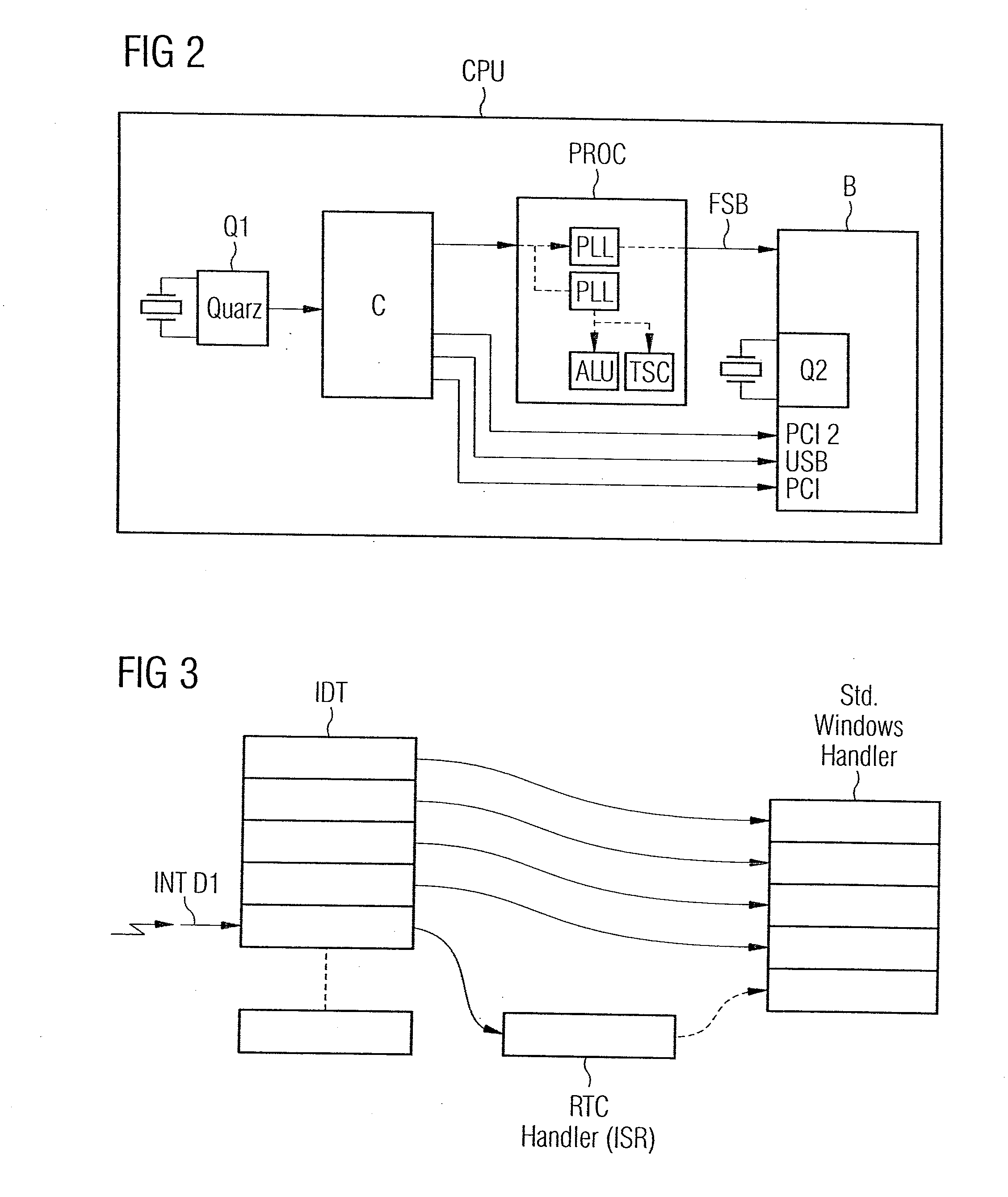
[0024]The real-time clock (RTC) crystal Q2 is visible in the right branch of FIG. 1, where the RTC crystal Q2 generates a clock of 32,768 kHz. The software counter (SWC) is counted up or down using an interrupt service routine (ISR), which is called up every 122.07 μs by the interrupt. This counter value can be read out over ...


PUM


Abstract

A method for enabling an oscillating crystal available in a system to be used to generate a software-realized time function, and an apparatus for implementing the method, without requiring additional hardware components, wherein a periodic interrupt signal is generated by the system-internal real-time clock, a table entry with a reference to a routine in an intra-system table is accessed upon receipt of the periodic interrupt signal and a counter is formed by the routine.

Description

BACKGROUND OF THE INVENTION[0001]1. Field of the Invention[0002]The present invention is directed to providing a failsafe time function in multiple systems in which different devices interact, where a standard time function that is available in the system is typically adjusted by a further independent timer, such as a monitoring timer or F-timer.[0003]2. Description of the Related Art[0004]The demands placed on the accuracy of the time signal are very high in the instances described, i.e., only a minimal fault and / or deviation tolerance is provided. The most well know counter is a timestamp counter (TSC), introduced with the ×86 Pentium processors and since then featured in all CPU designs. This is a 64 bit register, the value of which is incremented with the CPU clock, and can also be read out from the kernel space and / or from the user space.[0005]A second timer (i.e., an F-timer) hitherto had to be integrated to solve the problem of providing an accurate time signal. To this end, ...

Claims


Application Information

Patent Timeline
Patent Type & Authority Applications(United States)
IPC IPC(8): G06F1/14G06F1/04
CPCG06F1/14
Inventor EYERMANN, PAULLABOULIERE, MICHAELSCHWARZ, ROBERTWALTER, MARKUSWEINERT, KAI
Owner SIEMENS AG
Why Eureka
Try Eureka