Method for automatically determining the direction installation of an electronic lock

a technology of electronic locks and directions, applied in the field of electronic locks, can solve the problems of inapplicability of existing electronic lock latches, inconvenience, disassembly and maintenance of electronic locks, etc., and achieve the effect of broadening the application scope and convenience of electronic locks

Active Publication Date: 2011-08-04
TAIWAN FU HSING INDAL
View PDF4 Cites 42 Cited by
  • Summary
  • Abstract
  • Description
  • Claims
  • Application Information

AI Technical Summary

Benefits of technology

[0003]The primary objective of the present invention is to provide a method for automatically determining the direction installation of an electronic lock, wherein the electronic lock has a latch and a rotational actuator capable of driving the latch. The method comprises the steps of (a) driving the rotational actuator to rotate toward a first direction, and determining whether the rotational actuator is capable of being rotated, if yes, continuing to step (b), otherwise jumping to step (c); (b) enabling the rotational actuator to rotate toward the first direction, and meantime the rotational actuator touched a first switch unit and a second switch unit, then determining which of the switch units is prior touched by the rotational actuator, and if the rotational actuator touches the first switch unit prior to the second switch unit thereby confirming the electronic lock is installed on the left-handed door, otherwise, if the rotational actuator touches the second switch unit prior to the first switch unit thereby confirming the electronic lock is installed on the right-handed door; and (c) enabling the rotational actuator to rotate toward a second direction, and meantime the rotational actuator touched the first switch unit and the second switch unit, then determining which of the switch units is prior touched by the rotational actuator, and if the rotational actuator touches the first switch unit prior to the second switch unit thereby confirming the electronic lock is installed on the right-handed door, otherwise, if the rotational actuator touches the second switch unit prior to the first switch unit thereby confirming the electronic lock is installed on the left-handed door. The present invention achieves automatic determination of the electronic lock installed on the left-handed or right-handed door by controlling the rotational directions of the rotational actuator and determining the touching sequence of the switch units, so as to enable the electronic lock to be adapted to both the left-handed door and right-handed door, thereby significantly broadening the application scope and convenience of the electronic lock.

Problems solved by technology

Therefore, when a lock with unmatched latch arrangement is wrongly bought, or when the opening side of a door plank has to be switch due to the changed spacial planning, the existing electronic lock latch is not applicable, and additional purchase of another electronic lock latch has to be made.
Thus, diseconomy and inconvenience ensue for changing the electronic lock.

Method used


Image

  • Method for automatically determining the direction installation of an electronic lock
  • Method for automatically determining the direction installation of an electronic lock
  • Method for automatically determining the direction installation of an electronic lock

Examples


Embodiment Construction

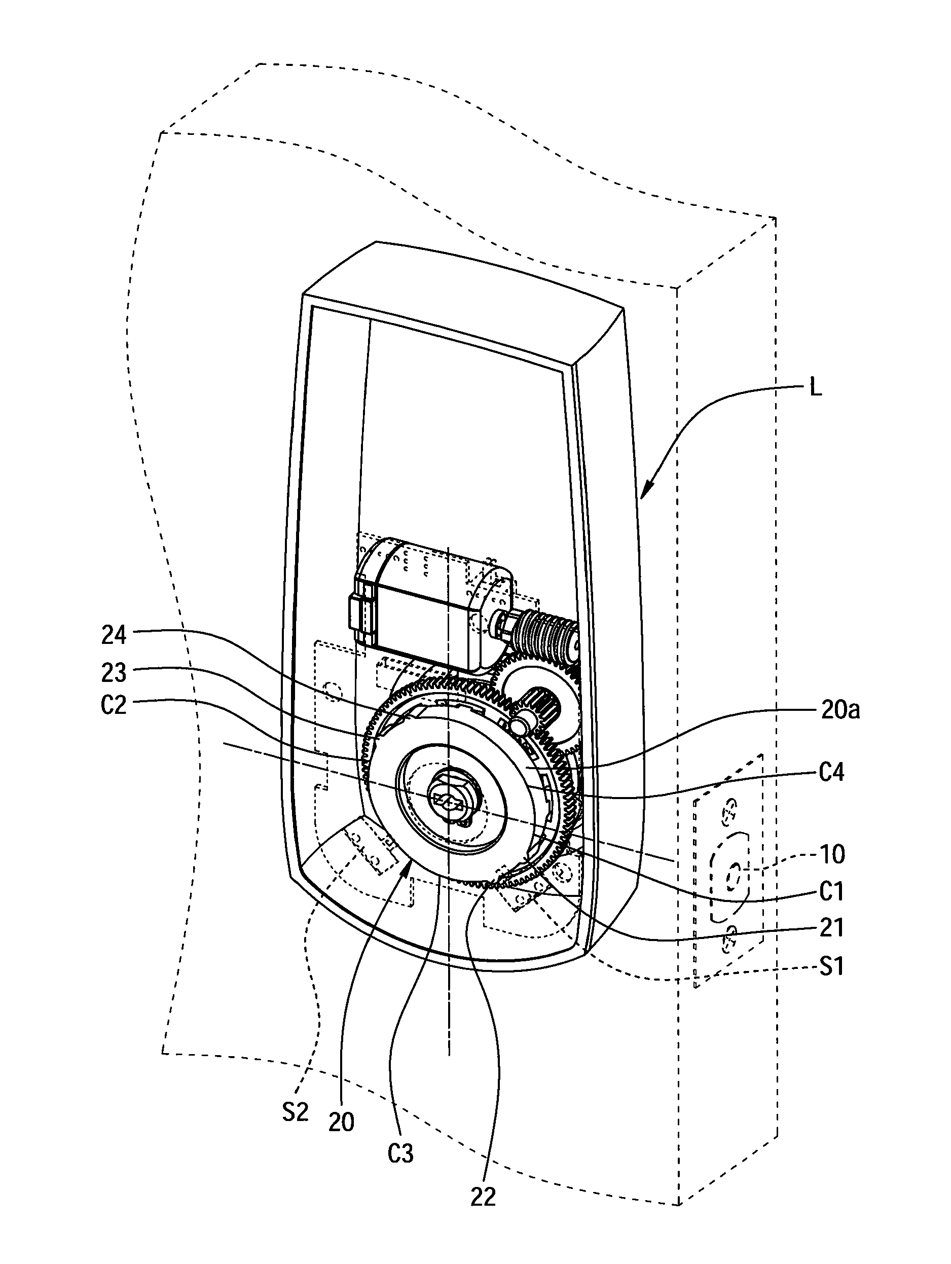
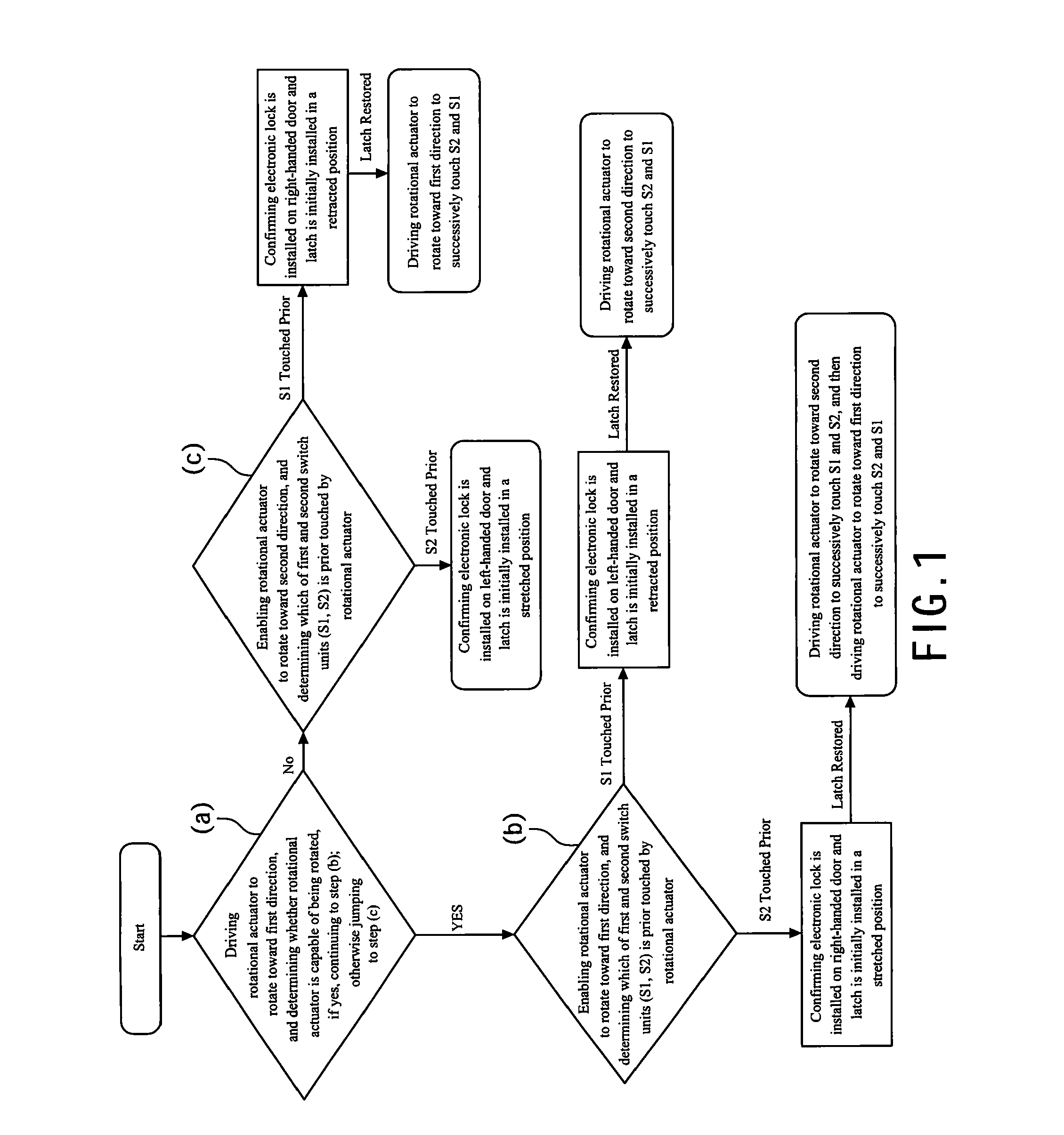
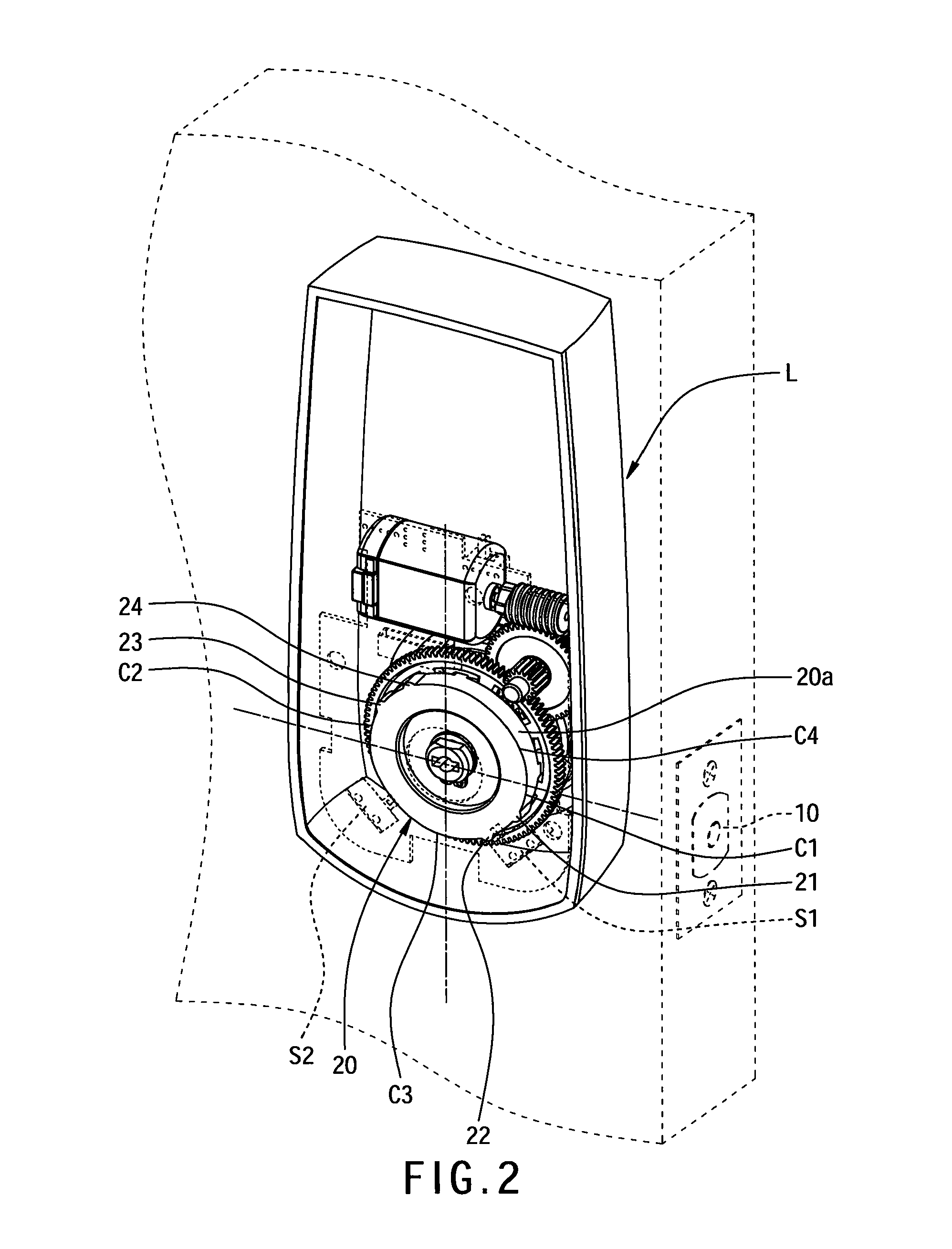
[0010]Referring to FIG. 1, a method for automatically determining the direction installation of an electronic lock according to one preferred embodiment of the present invention is illustrated. The method is particularly performed as below. First, referring to FIGS. 1 and 2, the electronic lock L has a latch 10, a rotational actuator 20 capable of driving the latch 10, a first switch unit 51 and a second switch unit S2. Referring to FIGS. 3A and 3C, the rotational actuator 20 is defined with a first direction R1 and a second direction R2 opposite to the first direction R1, and the rotational actuator 20 is capable of being rotated toward a first direction R1 or a second direction R2 to touch the first switch unit S1 and the second switch unit S2. Referring to FIGS. 2, 3A and 3C, in the present embodiment, the rotational actuator 20 has a peripheral surface 20a, a first protrusion 21, a second protrusion 22, a third protrusion 23 and a fourth protrusion 24. The peripheral surface 20a...


PUM


Abstract

A method for automatically determining the direction installation of an electronic lock is disclosed. The method achieves automatic determination of the electronic lock installed on the left-handed or right-handed door by controlling rotational directions of the rotational actuator and determining the touching sequence of switch units, so as to enable the electronic lock to be adapted to both the left-handed door and right-handed door, thereby significantly broadening the application scope and convenience of the electronic lock.

Description

FIELD OF THE INVENTION[0001]The present invention relates to an electronic lock, and more particularly to a method for automatically determining the direction installation of an electronic lock.BACKGROUND OF THE INVENTION[0002]For fitting spacial planning of buildings, there are left-handed doors and right-handed doors. Conventionally, electronic locks are designed with latches matching the opening sides of door planks (left-handed or right-handed), and installed directionally&differently according to the different opening sides of the doors where they are being installed. Therefore, when a lock with unmatched latch arrangement is wrongly bought, or when the opening side of a door plank has to be switch due to the changed spacial planning, the existing electronic lock latch is not applicable, and additional purchase of another electronic lock latch has to be made. Thus, diseconomy and inconvenience ensue for changing the electronic lock.SUMMARY[0003]The primary objective of the pres...

Claims


Application Information

Patent Timeline
Patent Type & Authority Applications(United States)
IPC IPC(8): B23P11/00E05B47/00E05B63/04
CPCB23P11/00E05B47/00Y10T29/49826Y10T29/49105E05B63/04Y10T70/7062Y10T70/5204E05B47/0012E05B2047/0067E05B2047/0069E05B2047/0091E05B2047/0068E05B2047/005E05B2047/002E05B2047/0094E05B17/22
Inventor HUANG, LIEN-HSILIN, SHIN-HAN
Owner TAIWAN FU HSING INDAL
Why Eureka
Try Eureka