Observation blind having decorative insulated panels and method for panel manufacture

a technology of decorative insulation panels and observation blinds, which is applied in the field of observation blinds or shelters, can solve problems such as rapid deterioration, and achieve the effects of increasing density and hardness, high hardness, and high polymer foam density

Inactive Publication Date: 2011-08-04
BOLIN JOEL W
View PDF0 Cites 16 Cited by
  • Summary
  • Abstract
  • Description
  • Claims
  • Application Information

AI Technical Summary

Benefits of technology

[0007]It is a principal feature of the present invention to provide a novel blind structure that is composed of thermally insulated wall panels to promote the comfort of the user even during uncomfortable weather conditions, particularly cold conditions where ice and snow may be present.
[0008]It is another feature of the present invention to provide a novel blind structure that is provided with decorative external surfaces that have the appearance of tree bark or are otherwise treated to have an external appearance that closely simulates the outdoor environment within which the blind is situated.
[0009]It is also a feature of the present invention to provide a novel blind structure that is composed of materials that resist damage or degradation resulting from the influence of weather conditions so that the blind structure will remain in serviceable condition for long periods of time without needing extensive maintenance or restoration.

Problems solved by technology

A primary disadvantage of this kind of homemade blind is that they are not particularly weather resistant, so that they deteriorate rapidly and must be extensively repaired or replaced within a couple of years.
However, the usual plastic covered wall panels provide virtually no thermal protection for the user; thus the user must dress according to the prevalent weather conditions as if located outdoors and must be prepared to accommodate abnormally high temperatures or wide ranges of temperatures especially on sunny days, since the dark plastic panels tend to absorb heat.

Method used


Image

  • Observation blind having decorative insulated panels and method for panel manufacture
  • Observation blind having decorative insulated panels and method for panel manufacture
  • Observation blind having decorative insulated panels and method for panel manufacture

Examples


Embodiment Construction

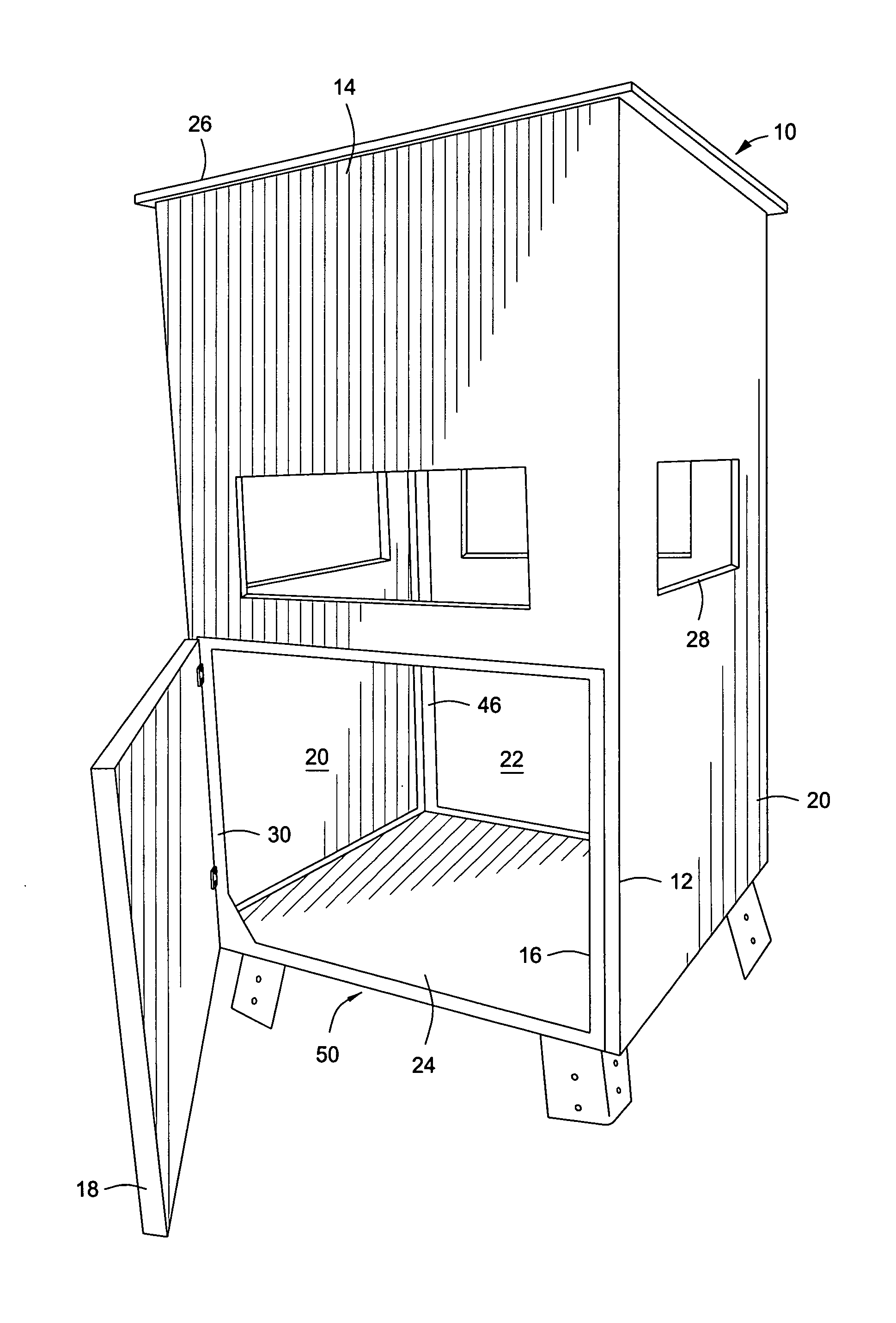
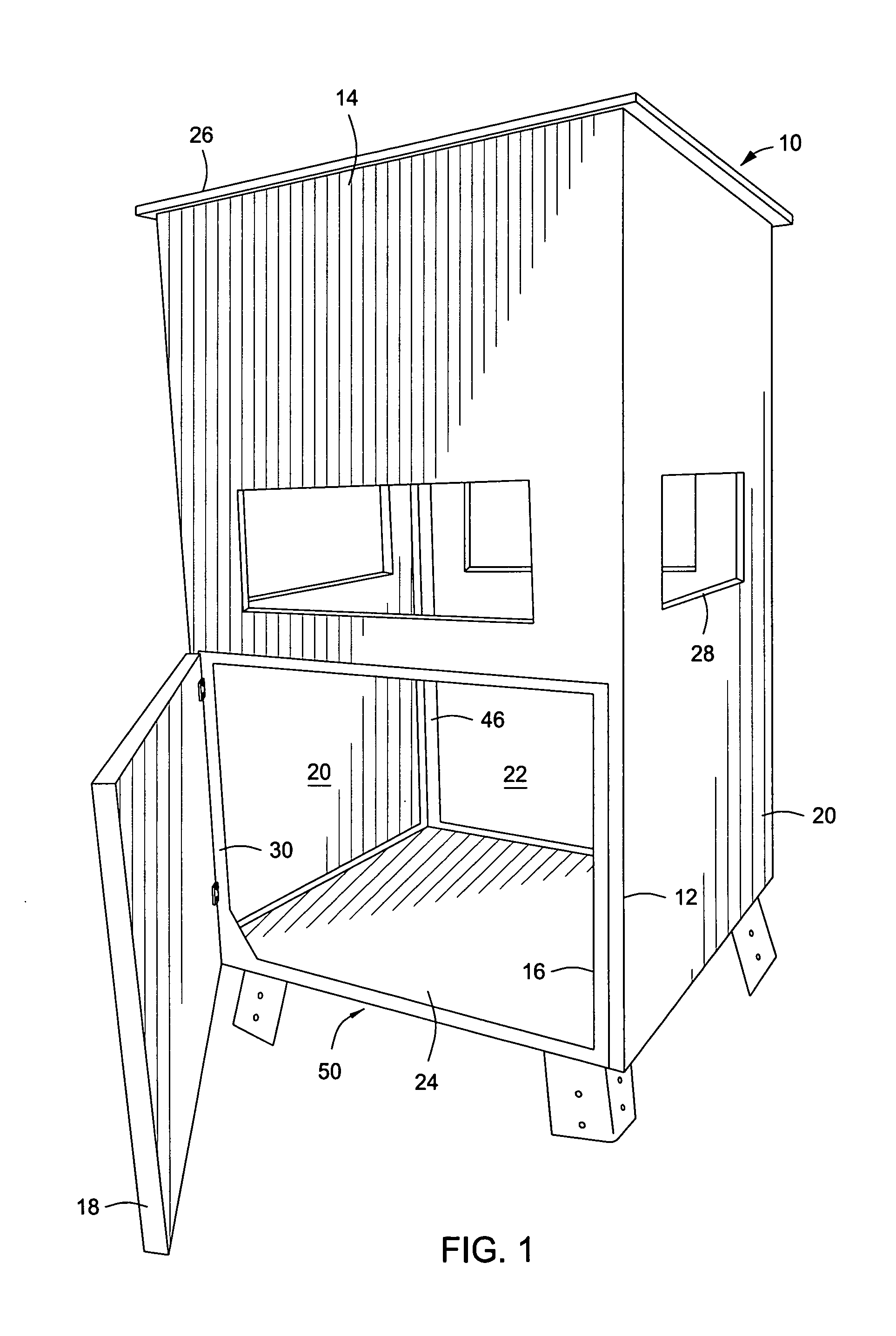
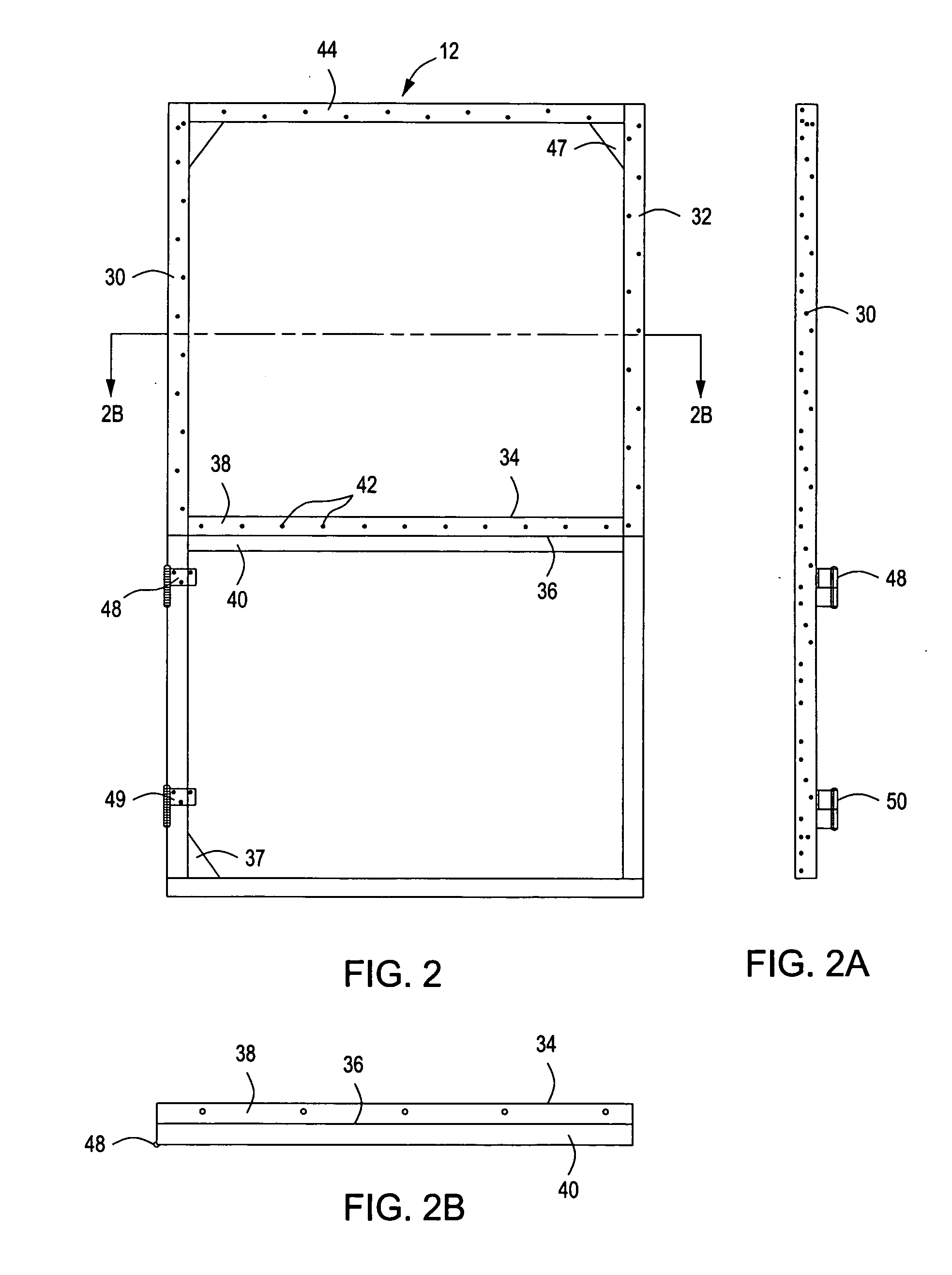
[0044]Referring now to the drawings and first to FIG. 1, a blind or shelter structure embodying the principles of the present invention is shown generally at 10 and has a substantially rigid framework shown generally at 12 that is preferably composed of steel framework members, but may be composed of any other suitable, substantially rigid framework members such as might be composed of a polymer material, wood or a suitable composite material. The blind structure 10 has a front wall having a front wall panel 14 defining a door opening 16, the door opening being closed by a pivotally mounted access door 18. The access door is shown to be substantially half the height of the front wall panel 14, but it is to be understood that the access door may extend substantially the full height of the wall panel. When a full height access door is employed the structural framework will not include intermediate horizontal structural members such as is shown at 34 and 40. The blind structure 10 also...


PUM

PropertyMeasurementUnit
transparentaaaaaaaaaa
resiliencyaaaaaaaaaa
tear resistanceaaaaaaaaaa

Abstract

A blind or shelter has a base structure with a framework mounted to the base structure and defines an access door opening. Composite wall and roof panels are mounted to the framework and have an intermediate structural core being embedded within a body of polymer foam material. At least some of the composite wall panels have window openings with window assemblies and define transparent moveable window panes for the window openings. An access door assembly is pivotally supported by the framework and is composed of a composite door panel formed of polymer foam material having a structural core panel embedded therein. The polymer foam is molded to have the appearance of faux tree bark or to have any other desired external appearance.

Description

BACKGROUND OF THE INVENTION[0001]1. Field of the Invention[0002]The present invention relates generally to observation blinds or shelters that are used for shelter and concealment of users for wildlife viewing during outdoor activities such as, photography, hunting, wildlife conservation and for numerous other similar outdoor activities. This invention also concerns the provision of blind structures having an external surface appearance that substantially simulates a wooded environment or other selected environment within which an observation blind is located, so that animals nearby will not be disturbed by the appearance of the blind and tend to avoid coming close to it. The blind structure has wall, door, windows, roof and floor components that provide efficient thermal insulation and resist damage and deterioration during a wide range of weather conditions. While the shelter structure of the present invention is referred to herein as an “observation blind”, it is to be understood...

Claims


Application Information

Patent Timeline
Patent Type & Authority Applications(United States)
IPC IPC(8): E04H15/34E04H15/56E04H15/54E04H15/58B29C44/02
CPCB29C44/02E04H15/34E04H15/58E04H15/56E04H15/54E04H1/1205A01M31/025E04H15/001E04B1/34321
Inventor BOLIN, JOEL W.
Owner BOLIN JOEL W
Why Eureka
Try Eureka