Bus bar attaching member and room lamp for vehicle having bus bar attaching member

Inactive Publication Date: 2011-08-04
YAZAKI CORP
View PDF7 Cites 8 Cited by
  • Summary
  • Abstract
  • Description
  • Claims
  • Application Information

AI Technical Summary

Benefits of technology

[0020]According to the invention of the first aspect of the defined in the first aspect of the invention, since the wiring part includes an impact absorbing part that prevents an impact when the electric wire is pressed in contact with the pressure contact blades from being transmitted to the parts attaching part in a part located between the bottom wall and the parts attaching part; and the impact absorbing part is formed by a first absorbing part extending from a part in the vicinity of the bottom wall in the direction intersecting a virtual straight line that connects the bottom wall to the parts attaching part, a second absorbing part extending to the parts attaching part side along the direction intersecting the first absorbing part from an end part of the first absorbing part separating from the bottom wall and a third absorbing part extending in the direction intersecting the second absorbing part from an end part of the second absorbing part separating from the first absorbing part, the bus bar attaching member can be provided in which the impact during the pressure contact of the electric wire is hardly transmitted to the parts attaching part, so that the electronic parts can be preve

Problems solved by technology

However, the usual room lamp for a vehicle having the above-described bus bar 103 has below-described problems.
Further, there is a problem that the holding property of the bulb attached to the one pair of parts attaching parts 107 may be possibly deteriorated due to the deformation.
Thus, a problem arises that attaching conditions to the vehicle are severely restricted.
Further, when the above-described bus bar 103

Method used


Image

  • Bus bar attaching member and room lamp for vehicle having bus bar attaching member
  • Bus bar attaching member and room lamp for vehicle having bus bar attaching member
  • Bus bar attaching member and room lamp for vehicle having bus bar attaching member

Examples


first embodiment

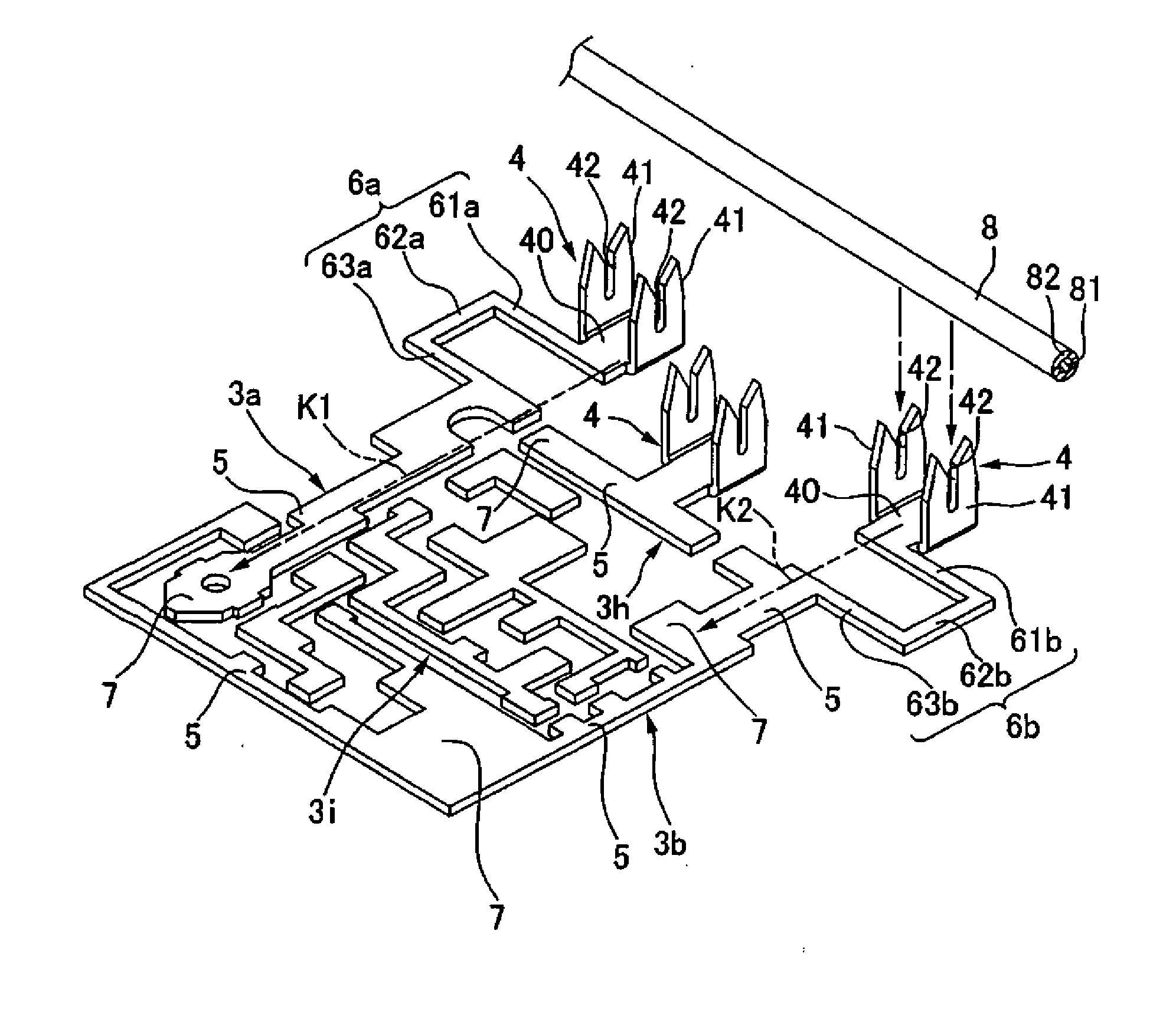
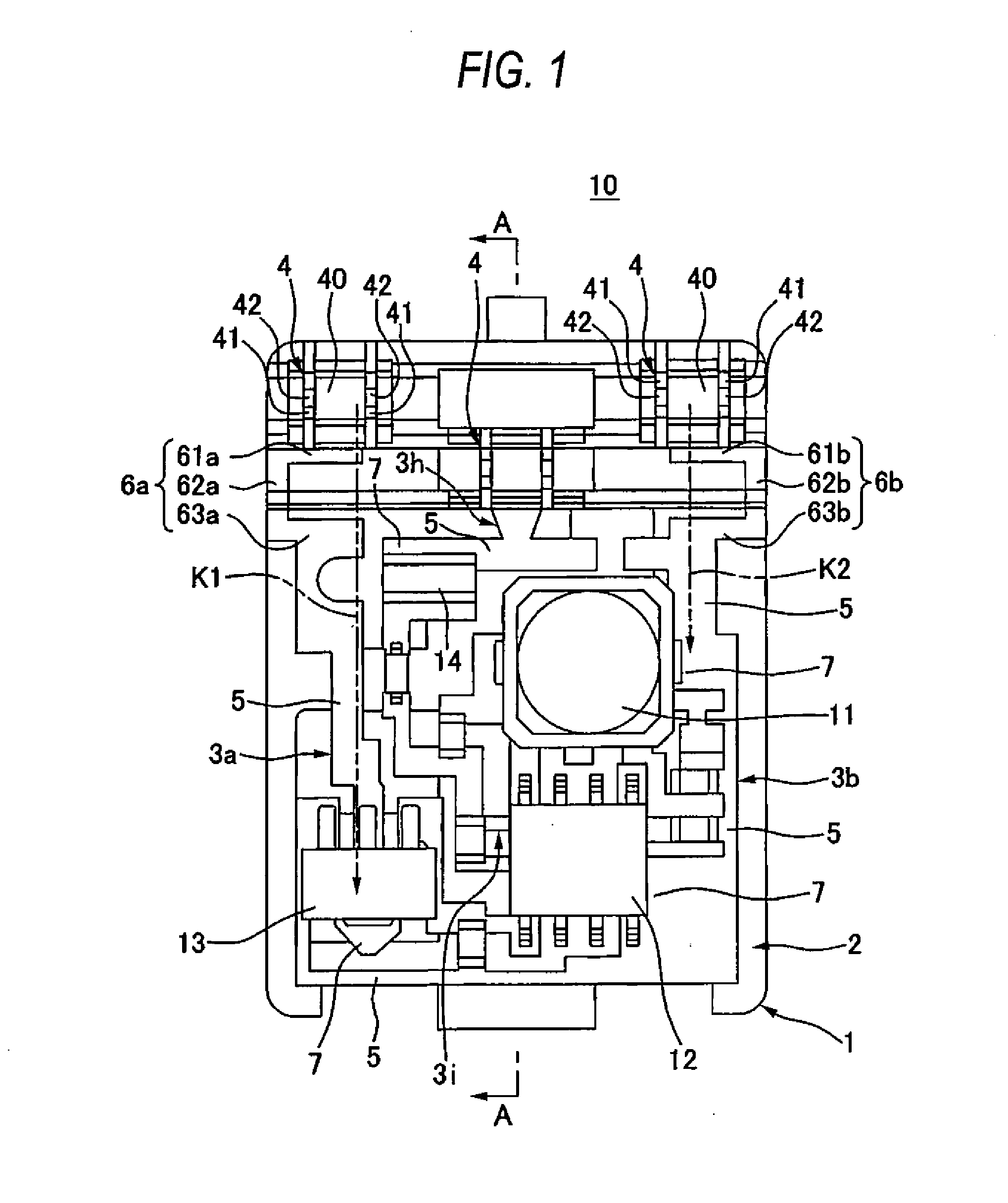
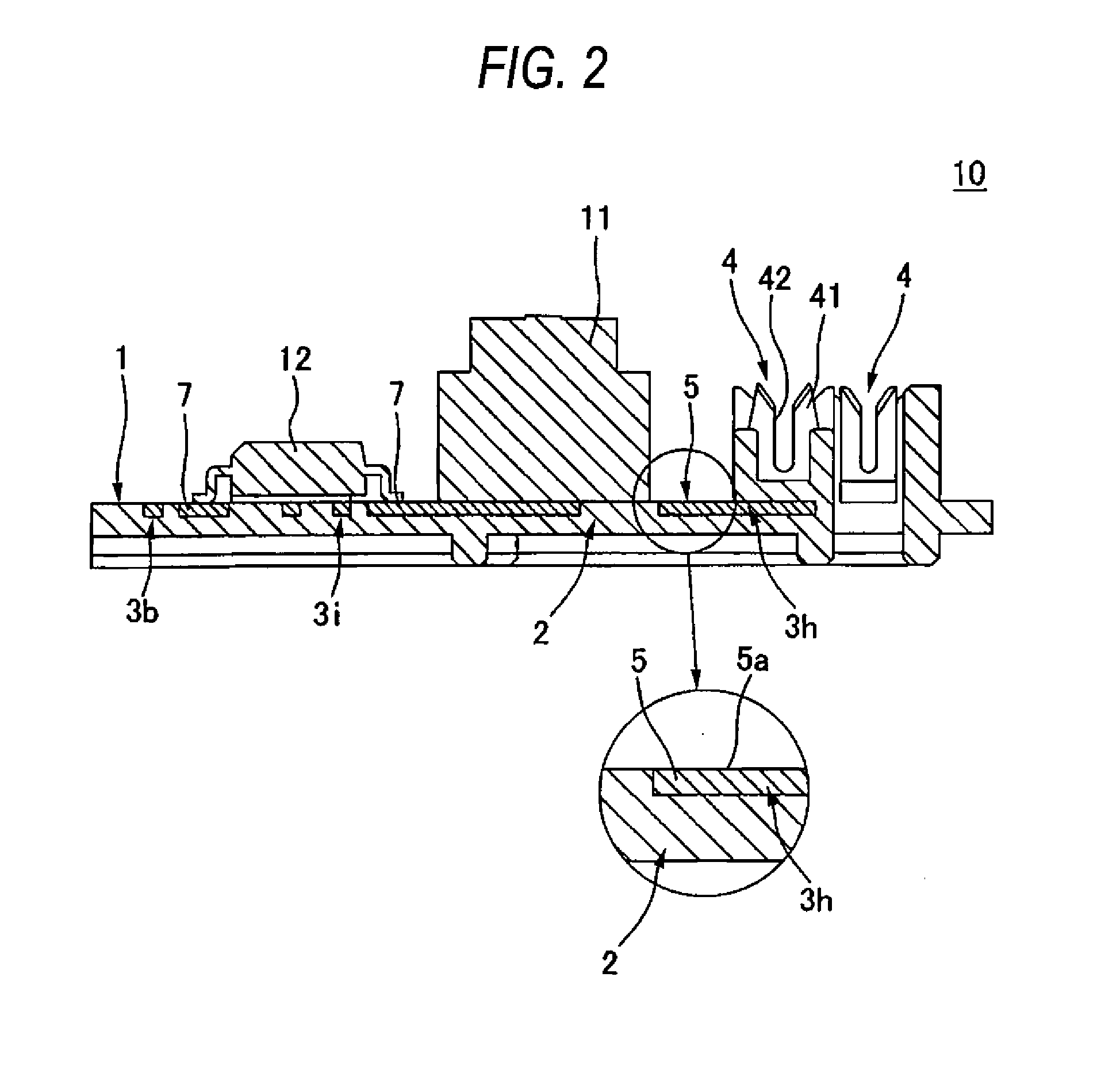
[0030]A “room lamp 10 for a vehicle” having a “bus bar attaching member 1” according to a first embodiment of the present invention will be described by referring to FIG. 1 to FIG. 3. The room lamp 10 for a vehicle of the present invention is a device attached to an opening for attaching the lamp provided in a roof trim as an internal wall material for covering a vehicle body panel of a motor vehicle to light an occupant's room of the motor vehicle.

[0031]As shown in FIG. 1 and FIG. 2, in the room lamp 10 for a vehicle, are provided a bus bar attaching member 1 in which a plurality of bus bars 3a, 3b, 3h and 3i are insert molded to a housing 2 made of a synthetic resin, a plurality of electronic parts 11, 12, 13 and 14 mounted on the surfaces of the plurality of bus bars 3a, 3b, 3h and 3i, a switch for turning on and off the room lamp 10 for a vehicle which is not shown in the drawing and a cover attached to the housing 2 which is not shown in the drawing. The electronic parts 11 is ...

second embodiment

[0049]A “bus bar attaching member” according to a second embodiment of the present invention is described by referring to FIG. 4. In FIG. 4, the same components as those of the above-described first embodiment are designated by the same reference numerals and an explanation thereof will be omitted.

[0050]In the bus bar attaching member of the present embodiment, bus bars 3c and 3d including impact absorbing parts 6c and 6d shown in FIG. 4 are provided in place of the bus bars 3a and 3b of the above-described bus bar attaching member 1 (see FIG. 1). Other structures are the same as those of the bus bar attaching member 1.

[0051]The above-described impact absorbing parts 6c and 6d are formed by bending wiring parts 5. Namely, the impact absorbing parts 6c and 6d are configured in U shaped forms by first absorbing parts 61c and 61d standing upright in the same directions as those of pressure contact blades 41 from parts in the vicinity of bottom walls 40 and extending in the directions i...


PUM


Abstract

A bus bar attaching member 1 forming a room lamp 10 for a vehicle includes a housing 2 and a plurality of bus bars 3a, 3b, 3h and 3i insert molded in the housing 2. Further, in wiring parts 5 of the bus bars 3a and 3b, impact absorbing parts 6a and 6b are provided that prevent an impact when an electric wire 8 is pressed in contact with pressure contact parts 4 from being transmitted to parts attaching parts 7. The impact absorbing parts 6a and 6b are configured in U shaped forms by first absorbing parts 61a and 61b extending in the directions intersecting virtual straight lines K1 and K2 that connect bottom walls 40 of the pressure contact parts 4 to the parts attaching parts 7, second absorbing parts 62a and 62b and third absorbing parts 63a and 63b.

Description

BACKGROUND OF THE INVENTION[0001]1. Field of the Invention[0002]The present invention relates to a bus bar attaching member that a bus bar is insert molded to a housing and a room lamp for a vehicle having the bus bar attaching member.[0003]2. Description of the Related Art[0004]As a usual room lamp attached to a ceiling of a vehicle, a structure is known that a bus bar formed by punching and bending a metal plate is attached to a housing made of a synthetic resin (for instance, see patent literature 1). FIG. 6 is a perspective view showing a bus bar forming the usual room lamp for a vehicle.[0005]As shown in FIG. 6, the bus bar 103 includes a plurality of press-contact parts 104 with which an electric wire is pressed in contact, a pair of parts attached parts 107 to which a bulb as a light source is attached, a plurality of contact point parts 108 that are electrically connected to a switch for turning on and off the supply of an electric power to the bulbs from the electric wire, ...

Claims


Application Information

Patent Timeline
IPC IPC(8): H02G5/00F21W106/00
CPCB60Q3/0203H01R43/24H01R4/2454B60Q3/0279B60Q3/51B60Q3/74
Inventor YOSHIDA, KOSUKE
Owner YAZAKI CORP
Why Eureka
Try Eureka