This helps you quickly interpret patents by identifying the three key elements:
Problems solved by technology
Method used
Benefits of technology
Benefits of technology
[0021] When the above is taken into consideration, it is preferable to perform background formatting in such a manner that the formatted portions are more effectively used, so that the formatting time at the time of disc ejection can be shortened more effectively.
[0024] In the manner described above, as a result of performing background formatting in an order opposite to the order in which user data is recorded, it is possible to make the formatted portions less likely to be overwritten by user data. As a result, background-formatted portions can be effectively used.
[0028] As described above, according to an embodiment of the present invention, background-formatted portions can be more effectively used, enabling portions that should be formatted at the ejection time to be smaller in number.
[0029] As a result, according to an embodiment of the present invention, when compared to the case of the related art, the time necessary for formatting, which should be performed when an optical disc recording medium is ejected, can be shortened.
Problems solved by technology
However, in the background formatting technique of the related art, since formatting is performed in accordance with the order in which user data is recorded as described with reference to FIG. 11, the formatted portions are likely to not be effectively used.
That is, in the case of an example shown in FIG. 12, only the section between the user data UD1 and the user data UD2 is effectively used, and the other portions becomes uselessly formatted portions as a result of the user data UD being overwritten.
Method used
Image
Click on the blue label to locate the original text in one second.
Reading with bidirectional positioning of images and text.
Examples
first embodiment
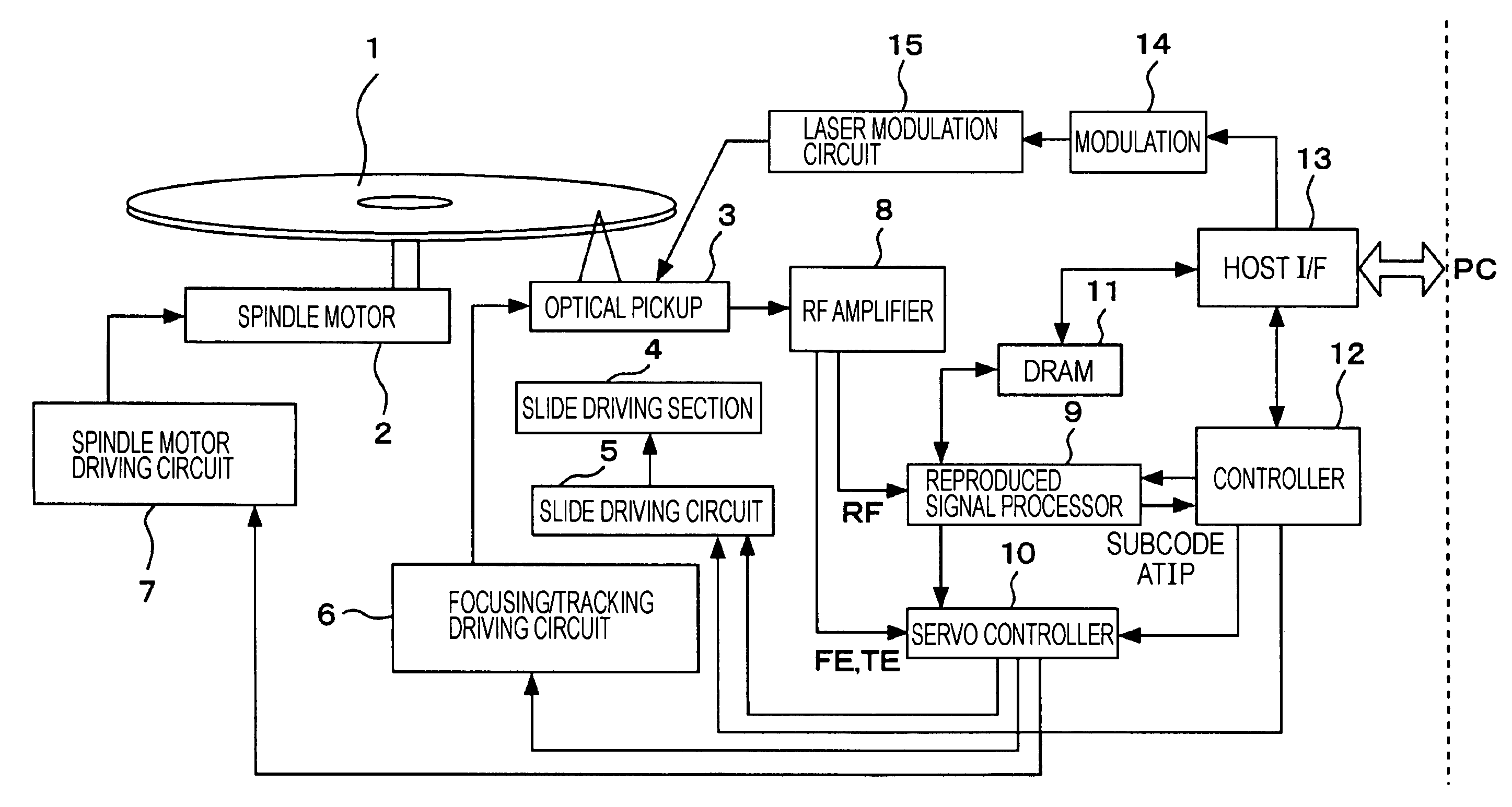
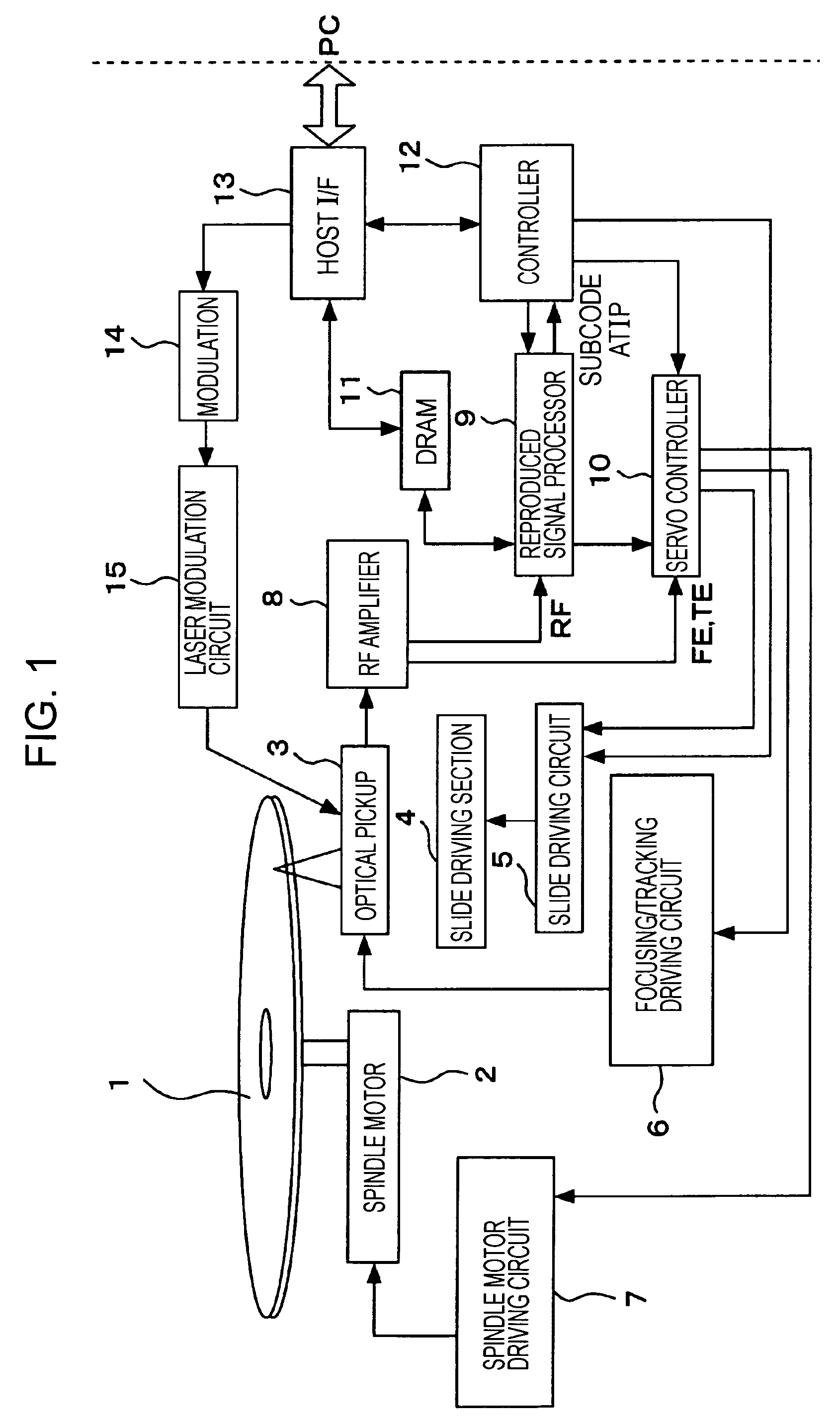
[0043]FIG. 1 is a block diagram showing the internal configuration of a disk drive apparatus, which is a recording apparatus, according to a first embodiment of the present invention.
[0044] A disc 1 shown in FIG. 1 is a data-rewritable disc of DVD (Digital Versatile Disc) system, having only one recording layer. More specifically, the disc 1 is a DVD+RW disc. In this case, the recording layer of the disk 1 is formed as a phase-change recording film.
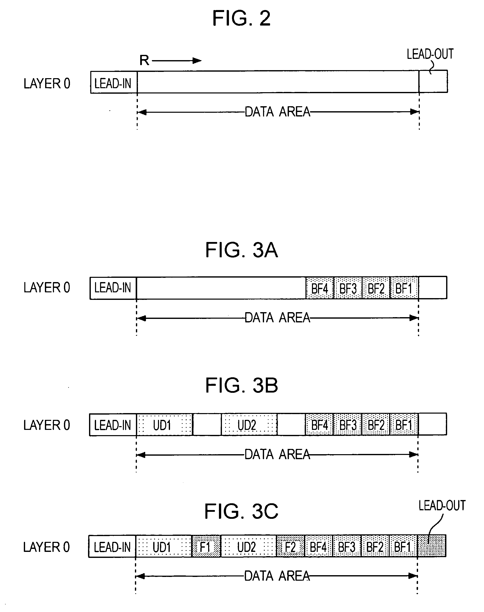
[0045] The area structure of the disk 1 in this case is as shown below in FIG. 2.
[0046] A lead-in area shown in FIG. 2 is located in the innermost peripheral portion of the disc 1. In the lead-in area, various kinds of information necessary for recording to and reproducing from the disc 1, such as information indicating the medium type of the disc 1 and management information, are recorded.
[0047] On the portion outside the lead-in area, a data area follows. This data area is an area where user data should be recorded. In the data area...
second embodiment
[0109] Up to this point, operations corresponding to a case in which the disc 1 is a single-layer disc having only one recording layer have been described. Alternatively, the disc 1 may be assumed to be a multi-layer disc having a plurality of recording layers.
[0110]FIG. 6 shows the cross-sectional structure of the disc 1, which is such a multi-layer disc.
[0111] The disc 1 in this case is configured as a data-rewritable multi-layer DVD+RW disc having a plurality of recording layers.
[0112] For the sake of description, the disc 1 is provided with only two recording layers: a first recording layer (layer 0) and a second recording layer (layer 1).
[0113] In this case, the two recording layers are phase-change recording films, and the two recording layers are layered with a comparatively small spacing.
[0114] As shown in FIG. 6, the first recording layer is closer to an objective lens 3a inside the optical pickup 3 of the disc drive apparatus, and the second recording layer is farther...
PUM
Abstract
A recording apparatus for performing recording on a data-rewritable recording medium having at least one recording layer includes a recorder configured to record data on the recording layer; and a controller configured to control the recorder so that dummy data is recorded in an order opposite to the order in which user data is recorded.
Description
CROSS REFERENCES TO RELATED APPLICATIONS [0001] The present invention contains subject matter related to Japanese Patent Application JP 2005-246059 filed in the Japanese Patent Office on Aug. 26, 2005, the entire contents of which are incorporated herein by reference. BACKGROUND OF THE INVENTION [0002] 1. Field of the Invention [0003] The present invention relates to a recording apparatus for performing recording on an optical disc recording medium on which data can be rewritten and to a recording method for use with the recording apparatus. [0004] 2. Description of the Related Art [0005] As optical recording media capable of optically recording or reproducing information, optical discrecording media are known. [0006] As such optical discrecording media, digital versatile discs (DVDs) have become very popular. As DVDs, a play-only DVD-ROM disc in which information is recorded as a combination of embossed pits and lands, a DVD-R disc and a DVD+R disc on which one-time-only recordin...
Claims
Application Information
Patent Timeline
Application Date:The date an application was filed.
Publication Date:The date a patent or application was officially published.
First Publication Date:The earliest publication date of a patent with the same application number.
Issue Date:Publication date of the patent grant document.
PCT Entry Date:The Entry date of PCT National Phase.
Estimated Expiry Date:The statutory expiry date of a patent right according to the Patent Law, and it is the longest term of protection that the patent right can achieve without the termination of the patent right due to other reasons(Term extension factor has been taken into account ).
Invalid Date:Actual expiry date is based on effective date or publication date of legal transaction data of invalid patent.

