
Bearing unit, and motor using same

Inactive Publication Date: 2005-11-17
SONY CORP
View PDF5 Cites 7 Cited by
  • Summary
  • Abstract
  • Description
  • Claims
  • Application Information

AI Technical Summary

Benefits of technology

[0017] The present invention has another object to provide a bearing unit with a smaller number of parts, easier to assemble and more reliable and a motor using the bearing unit.
[0041] Further, the bearing unit according to the present invention may have formed in the housing a communication path that provides a communication of the inside of the housing where the thrust bearing supports the shaft at one end of the latter with outside of the housing. Because of such a communication path, air caused to stay inside the housing by an environmental change, such as a change in barometric pressure, temperature, etc., can be let to escape to outside the housing, so that it is possible to prevent the viscous fluid from leaking out of the housing.

Problems solved by technology

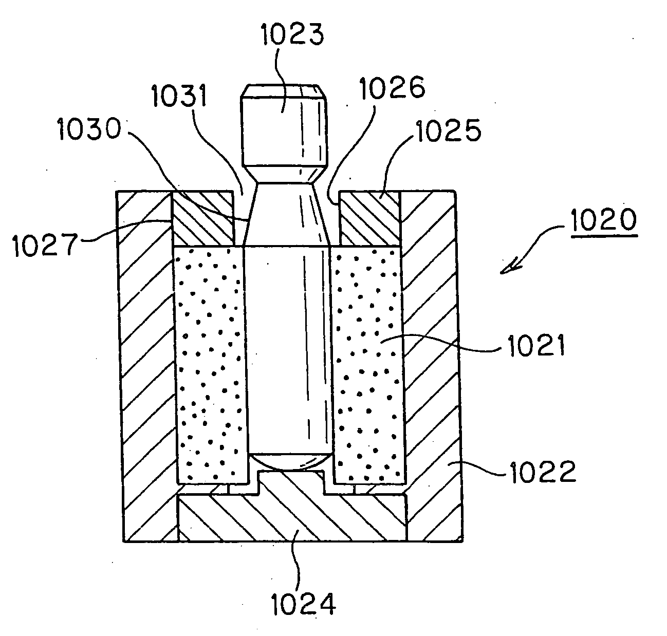
In addition, the sealant, such as an adhesive, has to be used to form the oil-tight junction 1027 between the housing 1022 and oil seal 1025, which will cause the assembling of the bearing unit 1020 to be complicated.
To prevent the lubricant from leaking, a surfactant has to be applied to the surface of the oil seal 1025, which also will make the production of a bearing unit of this type more complicated.
As mentioned above, the conventional bearing unit includes many parts and thus is difficult to assemble.
No positive sealing of the lubricant is possible.
Therefore, conventional bearing units are expensive.
Also, a motor using a bearing unit of the above-mentioned type will be an assembly of many parts, thus difficult to assemble, and so it is not producible with less costs.

Method used


Image

  • Bearing unit, and motor using same
  • Bearing unit, and motor using same
  • Bearing unit, and motor using same

Examples


third embodiment

[0200] The bearing unit provided with a come-off preventive mechanism is shown as the present invention in FIG. 19. It is generally indicated with a reference 80. As shown, the bearing unit 80 includes a housing 81 composed of a housing body 82 having the radial bearing 55 encased therein and a shaft end receptacle 83 in which the thrust bearing 66 is received. The shaft end receptacle 83 includes a housing bottom closer 84 having the thrust bearing 66 formed integrally therewith. The shaft end receptacle 83 is coupled integrally to the housing body 82 to form the housing 81. The housing 81 also is formed from a synthetic resin similarly to the aforementioned bearing units 30 and 70.

[0201] The housing body 82 has a shaft retainer 86 formed integrally at the bottom thereof to which the shaft end receptacle 83 is coupled. The shaft retainer 86 has formed in the center thereof a through-hole 85 in which there is inserted one end of the rotating shaft 51, on which the bottom end portion...

fourth embodiment

[0205]FIG. 20 shows the bearing unit according to the present invention. It is provided with a come-off preventive mechanism to prevent the rotating shaft from coming off the housing.

[0206] Note that in the following illustration and explanation, the same or similar elements of the bearing unit as those of the bearing unit 30 shown in FIGS. 5 and 6 will be indicated with the same or similar references as those in FIGS. 5 and 6 and will not be explained in detail.

[0207] The bearing unit is generally indicated with a reference 90. As shown in FIG. 20, the bearing unit 90 is provided with a come-off preventive mechanism to prevent the rotating shaft from coming off the housing. The come-off preventive mechanism is provided at the side of the housing 56 where the rotating shaft 51 projects. The bearing unit 90 has a shaft end receptacle 92 provided on the top portion 63 having the shaft insertion hole 65 in which the rotating shaft 51 is inserted and thus forming an oil seal.

[0208] Th...

fifth embodiment

[0265] The spindle motor 104 shown in FIG. 43 uses the bearing unit 160 including a housing 156 formed from an electroconductive resin having a electroconductive material mixed therein and which is constructed as shown in FIG. 44, which shows the bearing unit according to the present invention. The electroconductive resin is a polycarbonate, polyester, nylon, polyimide, liquid crystal or the like in which conductive carbon or metal powder is mixed. Also, a synthetic resin having electroconductive carbon nanotube mixed therein so as to be moldable with a high precision is used.

[0266] An electroconductive lubricant 157 is filled in the housing 156 formed from such an electroconductive resin. The lubricant 157 may be a machine oil such as esters, diesters, polyalphaolefin (PAO) or fluorinated machine oil in which an electroconductive material such as an electroconductive carbon compound is mixed.

[0267] The radial bearing 55 received in the housing 156 is formed from the above-mentione...


PUM


Abstract

A bearing unit is provided which includes a shaft (51) to support rotatably, radial bearing (55) to support the shaft (51) circumferentially, a thrust bearing (66) to support the shaft (51) in the direction of thrusting, and a housing (56) having the radial bearing (55) and thrust bearing (66) disposed therein and in which a viscous fluid (57) is filled. The housing (56) has a sealed structure except for a shaft insertion hole (65) formed therein and through which the shaft 51 is introduced. Between the outer surface of the shaft (51) and the inner surface of the shaft insertion hole (65), there is defined a gap (69) having a sufficient width to prevent the viscous fluid (57) filled in the housing (56) from leaking out of the latter. The housing (56) is formed as a one-piece structure by molding a synthetic resin.

Description

[0001] This is a continuation of application Ser. No. 10 / 416,838, filed on May 15, 2003, which is a 371 application of PCT / JP02 / 09360 filed on Sep. 12, 2002, the entire contents being incorporated by reference.TECHNICAL FIELD [0002] The present invention relates to a bearing unit for supporting a rotating shaft rotatably or for supporting a rotating body rotatably on a shaft and a motor using the bearing unit. BACKGROUND ART [0003] There are already known various types of bearing units for supporting a rotating shaft to be rotatable, including a typical one constructed as shown in FIG. 1. [0004] In FIG. 1, the bearing unit is generally indicated with a reference 1020. As shown, the bearing unit 1020 is to support a rotating shaft 1023 to be rotatable. It includes a metallic housing 1022 shaped as a cylinder open at opposite ends thereof and a radial bearing 1021 that supports the rotating shaft 1023 rotatably in the housing 1022. The housing 1022 has installed in one of the open end...

Claims


Application Information

Patent Timeline
IPC IPC(8): F16C17/02F16C17/04F16C17/10F16C17/26F16C29/06F16C32/06F16C33/10F16C33/20F16C35/02G11B19/20H02K5/16H02K7/08
CPCF16C17/026F16C17/107F16C33/103F16C33/107F16C41/008G11B19/2018H02K5/1677H02K7/085F16C2370/12F16C35/02F16C17/10
Inventor SHISHIDO, YUJIYAZAWA, KENICHIROKATO, SHINICHIROKIKUCHI, SHUICHIUJIIE, TORU
Owner SONY CORP
Learn More