

Dryer/Grinder
a dryer/grinder and coflow technology, which is applied in the direction of gas current separation, grain treatment, light and heating equipment, etc., can solve the problems of energy-inefficient and costly drying of materials to be processed in this manner, and undesirable moisture content of materials to be processed
- Summary
- Abstract
- Description
- Claims
- Application Information
AI Technical Summary
Problems solved by technology
Method used
Image

Examples
Embodiment Construction
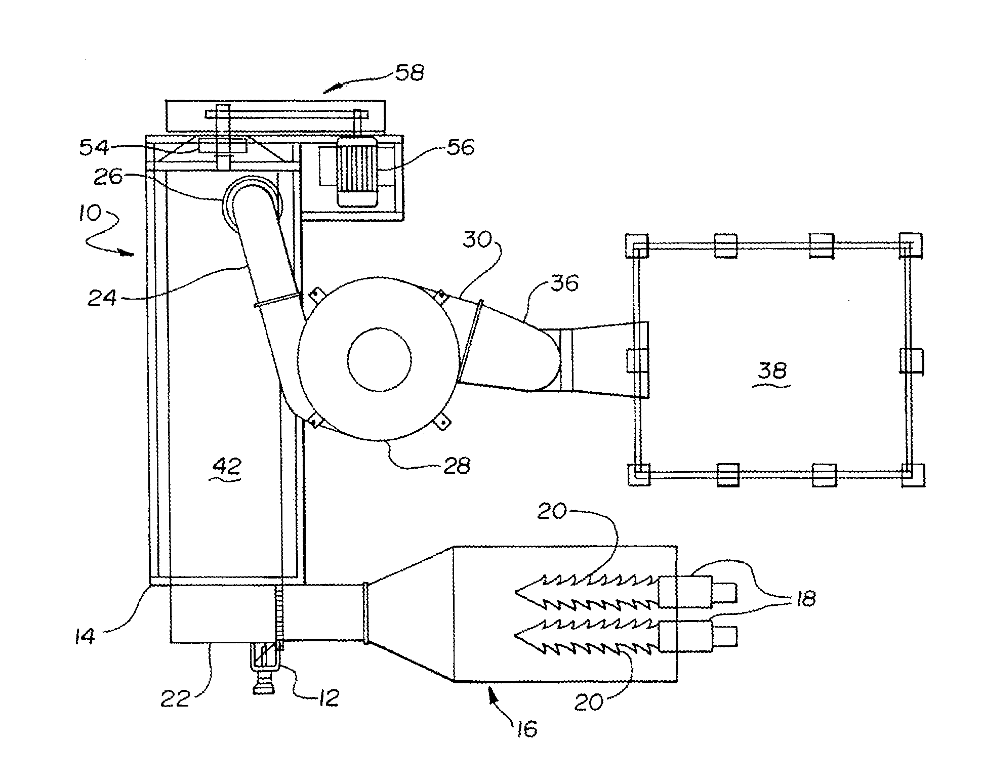
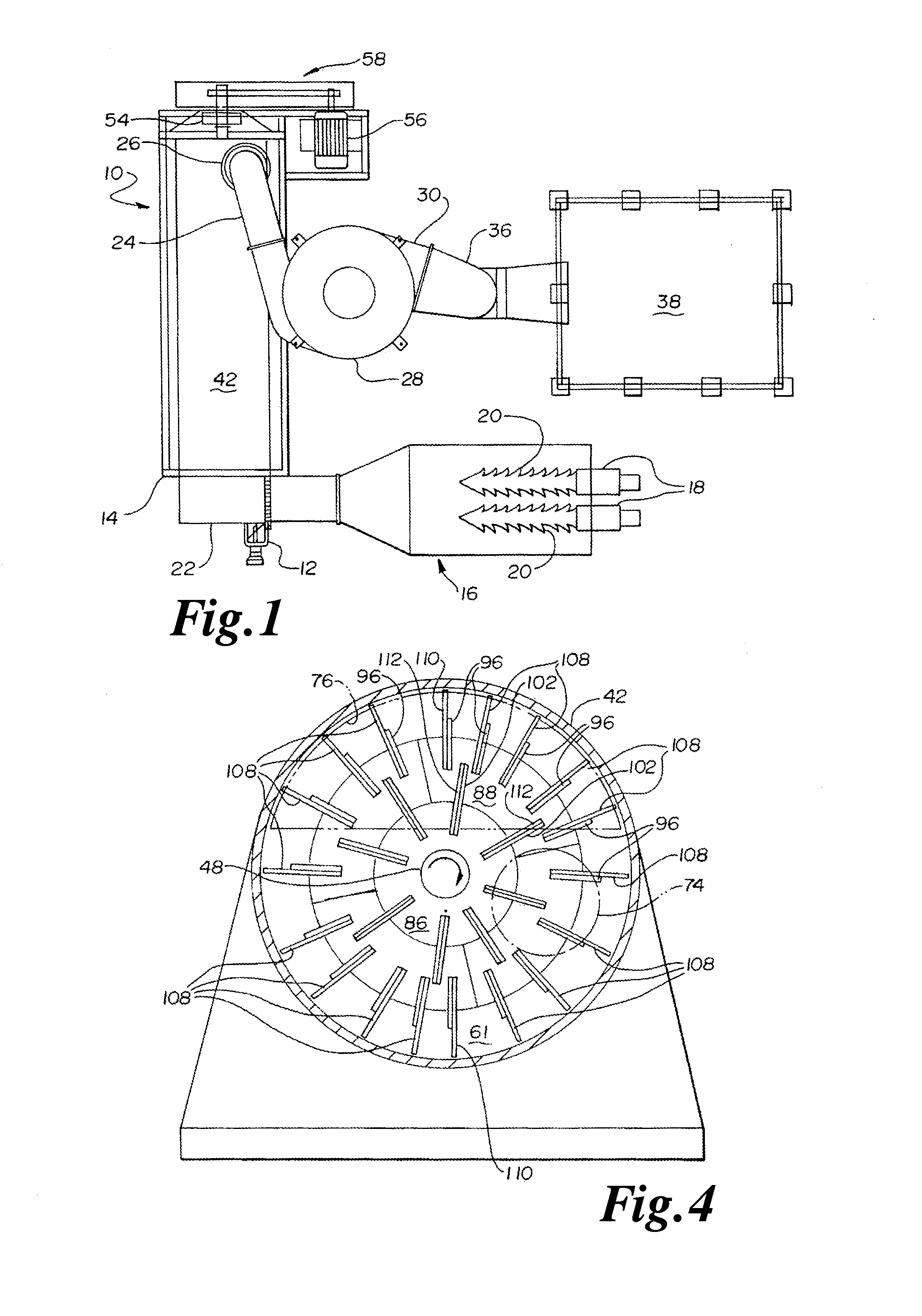
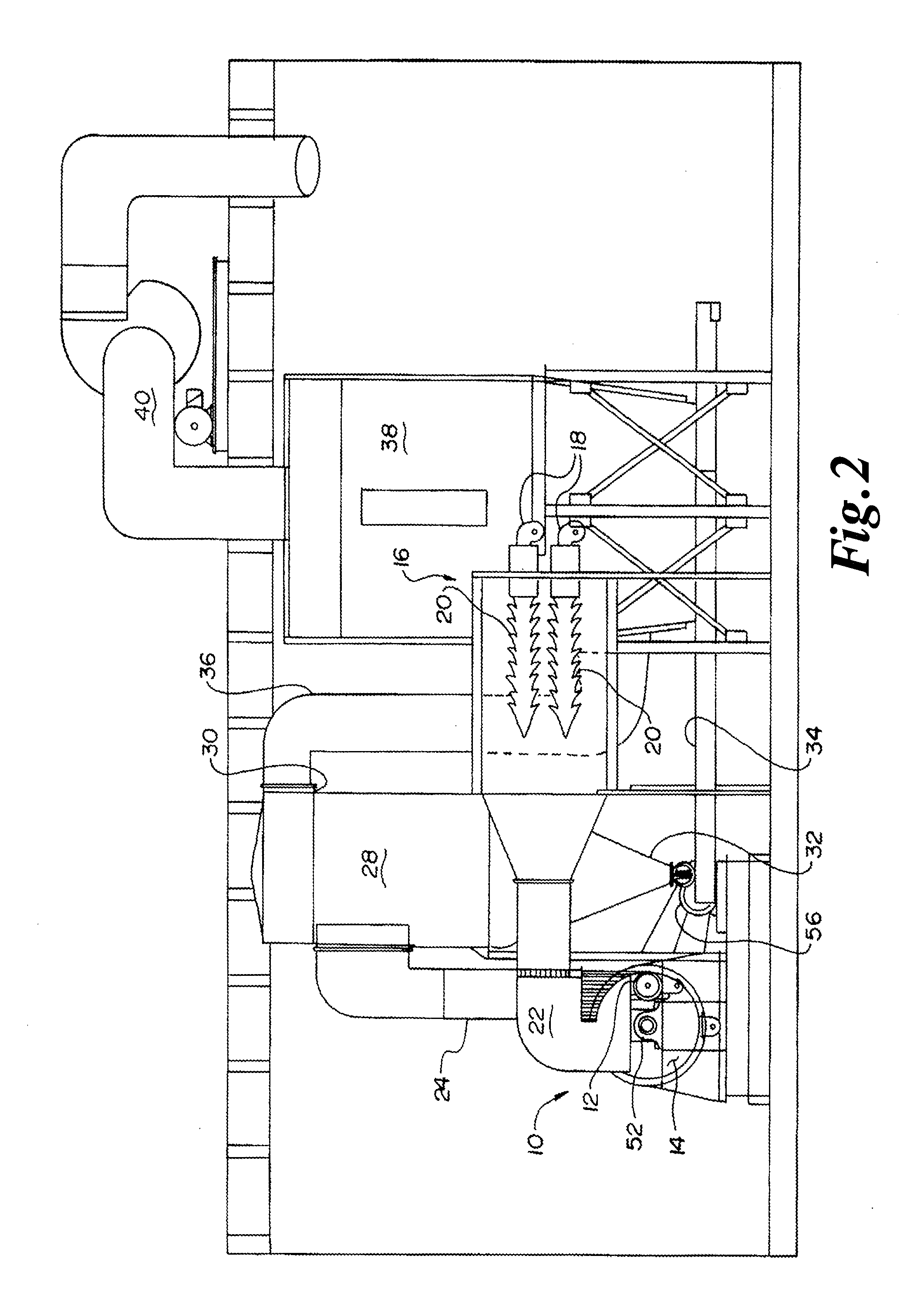
[0057]Referring now to the Figures, and most particularly to FIGS. 1, 2 and 15 a slurry dryer 10 may be seen, along with associated equipment useful in the practice of the present invention. The associated equipment in at least one embodiment may include a slurry feed pump 12 connected to an inlet end 14 of dryer 10 a source of hot air 16 which may include one or more blowers 18 and burners 20. Inlet end 14 may include an inlet hopper 15. The hot air is connected by an inlet air duct 22 to the inlet end 14 of dryer 10. An outlet duct 24 may be connected between an outlet 26 of dryer 10 and a conventional cyclone separator 28. Separator 28 may have an air outlet 30 and a material outlet 32. In at least one embodiment a material outlet 32 may be connected to a material delivery conveyor 34. Air outlet 30 may be connected by a duct 36 to a dust collector 38. Once the air is filtered by dust collector 38, it may be exhausted to atmosphere via duct 40.
[0058]Referring now also to FIG. 3, ...
PUM
 Abstract
Description
Claims
Application Information