Signal generation method and apparatus and test method and system using the same

Inactive Publication Date: 2011-08-04
NXP BV
View PDF10 Cites 0 Cited by
  • Summary
  • Abstract
  • Description
  • Claims
  • Application Information

AI Technical Summary

Benefits of technology

[0011]It is therefore an object of the present invention to provide a signal generation system and method of generati

Problems solved by technology

This increasing complexity has the associated issue of more complex and hence more expensive test.
This issue in view of testing is identified in the SIA roadmap for semiconductors as one of the key problems for present and future mixed-signal SoCs.
In addition, these analog parts or analog cores are normally very sensitive to noise and loading effects, which limit the internal monitoring and make their test a difficult task.
The use of the built-in self-test techniques (BIST techniques) can make a significant difference in terms of test time and costs in comparison to traditional testing with off-chip equipment.
The diversity of analog circuit design, the multitude of their performance parameters and their limited observability

Method used


Image

  • Signal generation method and apparatus and test method and system using the same
  • Signal generation method and apparatus and test method and system using the same
  • Signal generation method and apparatus and test method and system using the same

Examples


Example

DETAILED DESCRIPTION OF THE DRAWINGS

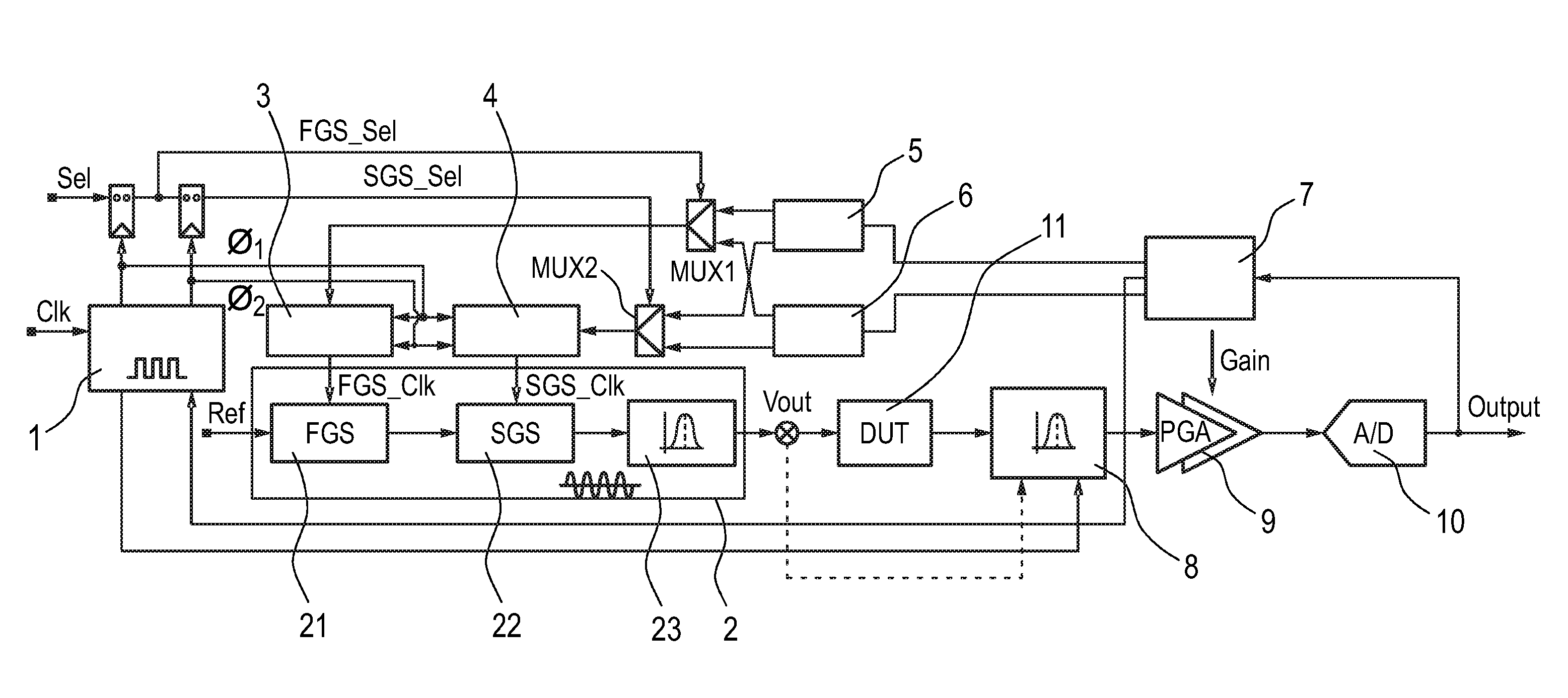
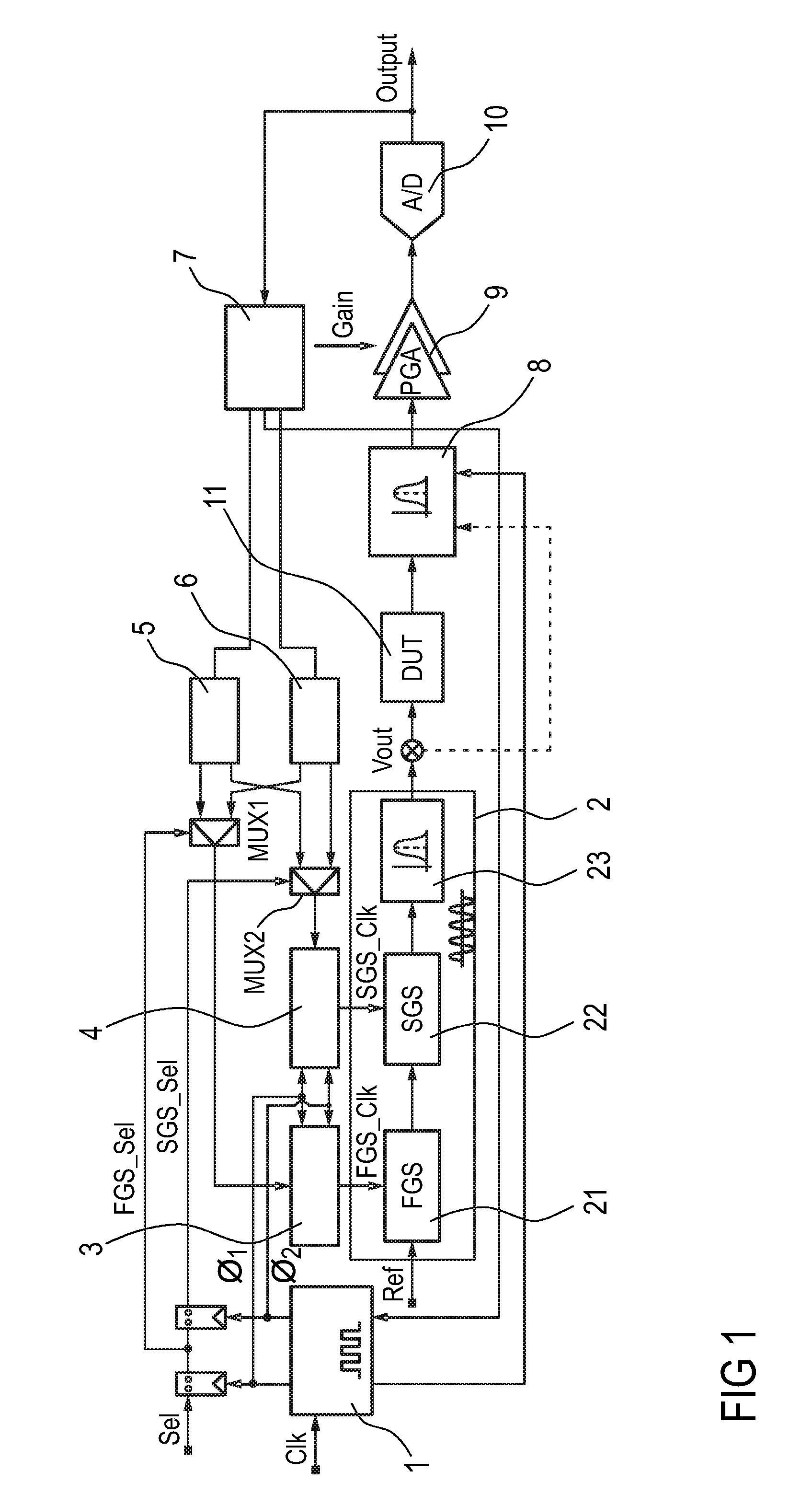
[0042]FIG. 1 shows a block diagram of the signal generation system according to the present invention for performing an on-chip generation of discrete-time periodic analog signals for analog circuits. The signal generation system consists of a non-overlapped clock generator 1, programmable (multi-) gain stage with a time-variant filter (analog filter) forming a programmable sine wave generator 2, clock mapping blocks including a (first) FGS clock mapping block or unit 3 as well as a (second) SGS clock mapping block or unit 4, gain decoders including a (first) FGS gain decoder 5 and a (second) SGS gain decoder 6, a digital control unit 7, a band pass filter 8, an additional programmable gain amplifier (PGA) 9 being supplied with the output (signals) of the band pass filter 8 to further improve the dynamic range of the system, and a final stage for the amplitude detection and / or digitization of the PGA output, such as an analog-to-digital converter ...


PUM


Abstract

According to a first aspect of the present invention there is provided a signal generation system for generating a predetermined analog signal. The system comprises a clock generator (1) adapted for generating on the basis of an external clock signal a predetermined clock signal, a signal generator including a first gain stage (21) and a second gain stage (22) adapted for providing an overall gain of the signal generator and outputting a stepped analog signal, an analog filter (23) adapted for filtering the stepped analog signal output by the second gain stage and for outputting the predetermined analog signal, and a first and a second clock mapping units (3,4) adapted for receiving the predetermined clock signal, and respectively supplying to the first and second gain stages non-overlapped clock signal, wherein the amount of gain provided by the first and second gain stages is controlled by the non-overlapped clock signals. The present invention further relates to a signal generation method of generating discrete-time periodic analog signals suitable for a built-in self-test, as well as to a test method and system using the same.

Description

FIELD OF THE INVENTION[0001]The present invention relates to a signal generation system and method of generating discrete-time periodic analog signals suitable for a built-in self-test BIT, as well as to a test method and system using the same.BACKGROUND OF THE INVENTION[0002]Nowadays, the constant evolution of the integration capability in CMOS technologies is making possible the development of complex-mixed signal SoC (SoC: System on Chip). This increasing complexity has the associated issue of more complex and hence more expensive test. This issue in view of testing is identified in the SIA roadmap for semiconductors as one of the key problems for present and future mixed-signal SoCs. Regarding the analog parts thereof, usually the test of these parts represents the main bottleneck in this line. Analog circuits are usually tested using functional approaches, often requiring a large data volume processing, high accuracy and high speed ATEs (ATE: Automatic Test Equipment). In addit...

Claims


Application Information

Patent Timeline
IPC IPC(8): H03K4/02
CPCH03K4/023
Inventor ZJALO, AMIR
Owner NXP BV
Why Eureka
Try Eureka