Method and apparatus for handover in wireless communication system

a wireless communication system and wireless communication technology, applied in electrical equipment, wireless commuication services, network traffic/resource management, etc., can solve the problems of rlf, ue is longer, and all ues cannot help with handover, so as to improve the quality of service

Active Publication Date: 2011-08-04
SAMSUNG ELECTRONICS CO LTD
View PDF5 Cites 62 Cited by
  • Summary
  • Abstract
  • Description
  • Claims
  • Application Information

AI Technical Summary

Benefits of technology

[0029]Accordingly, the present invention can advantageously enable the UE, which moves at a high rate, to perform the handover without the service interruption.

Problems solved by technology

Therefore, when the UEs move in a different movement speed equal to or higher than 120 km/h in the conventional wireless communication system, all of the UEs cannot help performing the handover based on the identical system parameter for each cell.
Further, the conventional handover has a problem in that the time for measuring RSRP (Reference Signal Received Power) and transmitting a measurement result to the serving eNB by the UE is longer than a movement time of the UE.
Therefore, the high-speed UE cannot perform the fast handover, such that it inevitably has a RLF (Radio Link Failure) problem of connection interruption of a wireless link during the performance of the handover.
Further, there a problem may occur in that the handover is first performed before the UE moves to a target cell, thereby resulting in the RLF.
Further, there a handover delay problem may occur in that even when the high-speed UE has moved to a location within the target cell, the handover is not performed, such that the RLF may b

Method used


Image

  • Method and apparatus for handover in wireless communication system
  • Method and apparatus for handover in wireless communication system
  • Method and apparatus for handover in wireless communication system

Examples


Embodiment Construction

[0042]FIGS. 1 through 10, discussed below, and the various embodiments used to describe the principles of the present disclosure in this patent document are by way of illustration only and should not be construed in anyway to limit the scope of the disclosure. Those skilled in the art will understand that the principles of the present disclosure may be implemented in any suitably arranged wireless communication system. In the following description, a detailed explanation of known related functions and constitutions may be omitted to avoid unnecessarily obscuring the subject matter of the present invention.

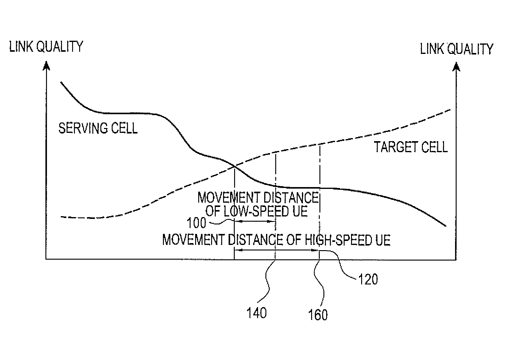
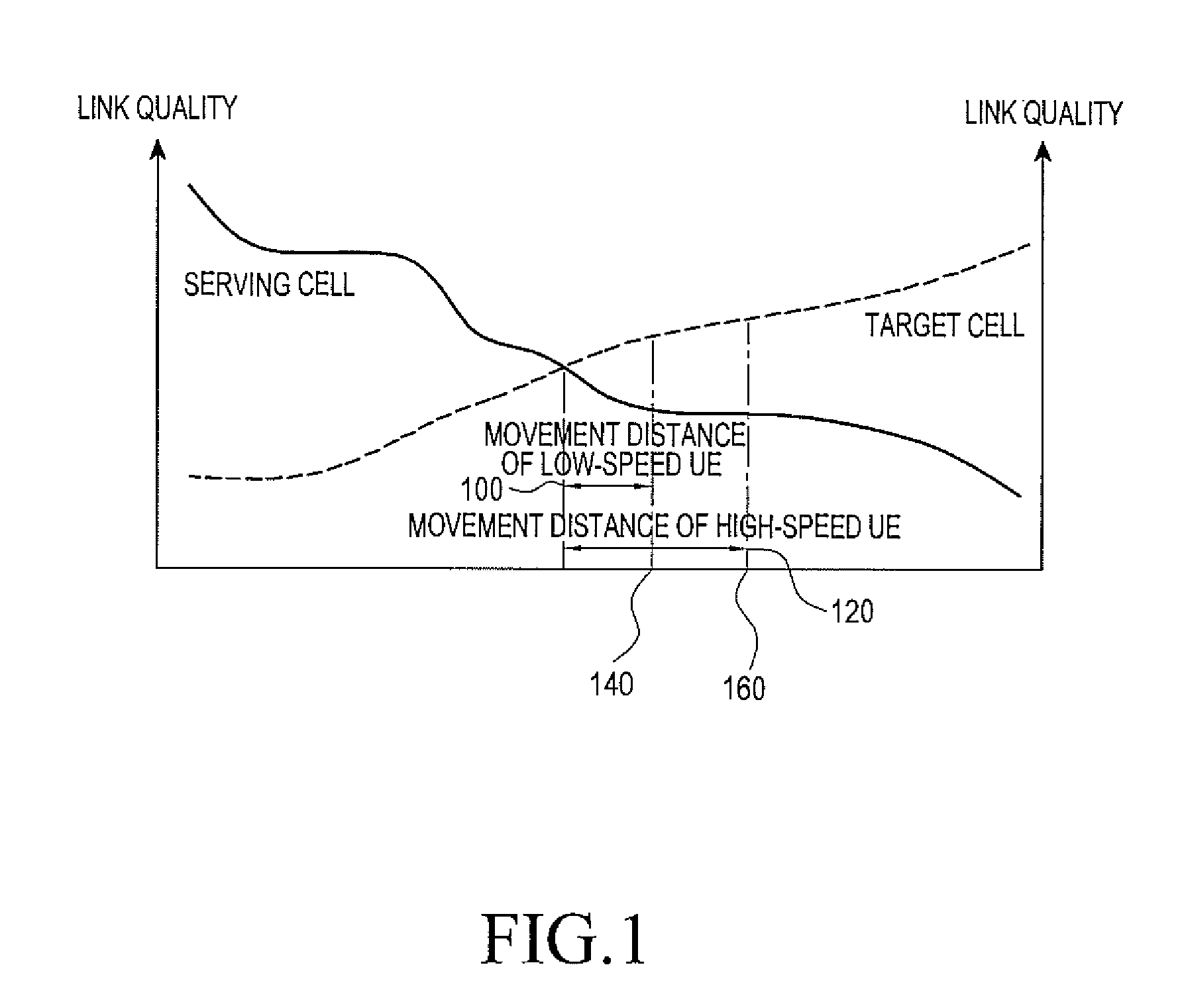
[0043]The present invention suggests a method and an apparatus for handover in a wireless communication system, e.g. an LTE (Long Term Evolution) communication system. Specifically, the present invention suggests a method and an apparatus which enables a User Equipment (UE) to more efficiently perform the handover without service interruption even when the UE moves at a high rate.

[...


PUM


Abstract

A method and an apparatus ensure efficient handover in a wireless communication system even when a User Equipment (UE) moves at a high speed. A serving eNB receives interference power information of an uplink (UL) signal and interference increase/decrease information of the UL signal from at least one adjacent eNB. an adjacent eNB, for which the received interference power information indicates that interference power of the UL signal is equal to or greater than a threshold value, is selected as a target eNB for a User Equipment (UE) among the at least one adjacent eNB. Whether handover of the UE is delayed is determined based on the interference increase/decrease information received from the target eNB. And if the handover of the UE is delayed, a handover parameter is transmitted to the UE to perform handover to the target eNB.

Description

CROSS-REFERENCE TO RELATED APPLICATION(S) AND CLAIM OF PRIORITY[0001]The present application is related to and claims priority under 35 U.S.C. §119(a) to a Korean Patent Application entitled “Method and Apparatus for Handover in Wireless Communication System” filed in the Korean Industrial Property Office on Feb. 4, 2010 and assigned Serial No. 10-2010-0010554, the contents of which are incorporated herein by reference.TECHNICAL FIELD OF THE INVENTION[0002]The present invention relates to a method and an apparatus for handover in a wireless communication system.BACKGROUND OF THE INVENTION[0003]In the LTE (Long Term Evolution), which is next generation communication technology, a downlink uses the OFDMA (Orthogonal Frequency-Division Multiple Access) and an uplink uses SC-FDMA (Single-Carrier Frequency Division Multiple Access) for the purpose of the transmission of high-rate data. The LTE provides the 3GPP (Third Generation Partnership Project) with competitive wireless access techn...

Claims


Application Information

Patent Timeline
IPC IPC(8): H04W36/00
CPCH04W28/04H04W36/0083H04W48/20H04W48/16H04W36/08H04W36/00837H04W36/0061H04W36/18H04W36/20H04W36/30
Inventor JEON, YOUNG-HYUNMIN, CHAN-HOLEE, JU-MIKIM, YUNG-SOOKWUN, JONG-HYUNG
Owner SAMSUNG ELECTRONICS CO LTD
Why Eureka
Try Eureka