Photovoltaic element

a technology of photovoltaic elements and piercings, applied in the field of photovoltaic elements, can solve the problems of increased work risks, relatively high conversion costs, and particularly risky application of piercing approaches

Inactive Publication Date: 2011-08-11
SIKA TECH AG +1
View PDF4 Cites 9 Cited by
  • Summary
  • Abstract
  • Description
  • Claims
  • Application Information

AI Technical Summary

Problems solved by technology

The sealing situation is very reliable, but this version can be relatively costly because two plastic sealing webs are used and applied.
Piercing approaches can be especially risky in application with respect to leaks, and can be expensive because they impose special demands on the technical approach and the professional ski

Method used


Image

  • Photovoltaic element
  • Photovoltaic element
  • Photovoltaic element

Examples


Embodiment Construction

[0018]A photovoltaic element is disclosed which for the most part exploits advantages of single-layer systems and two-layer systems and avoids their drawbacks.

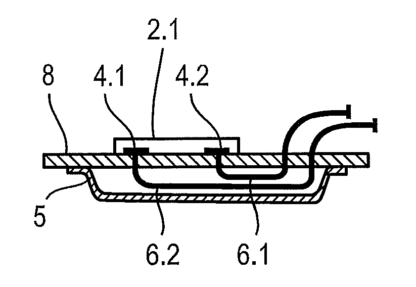
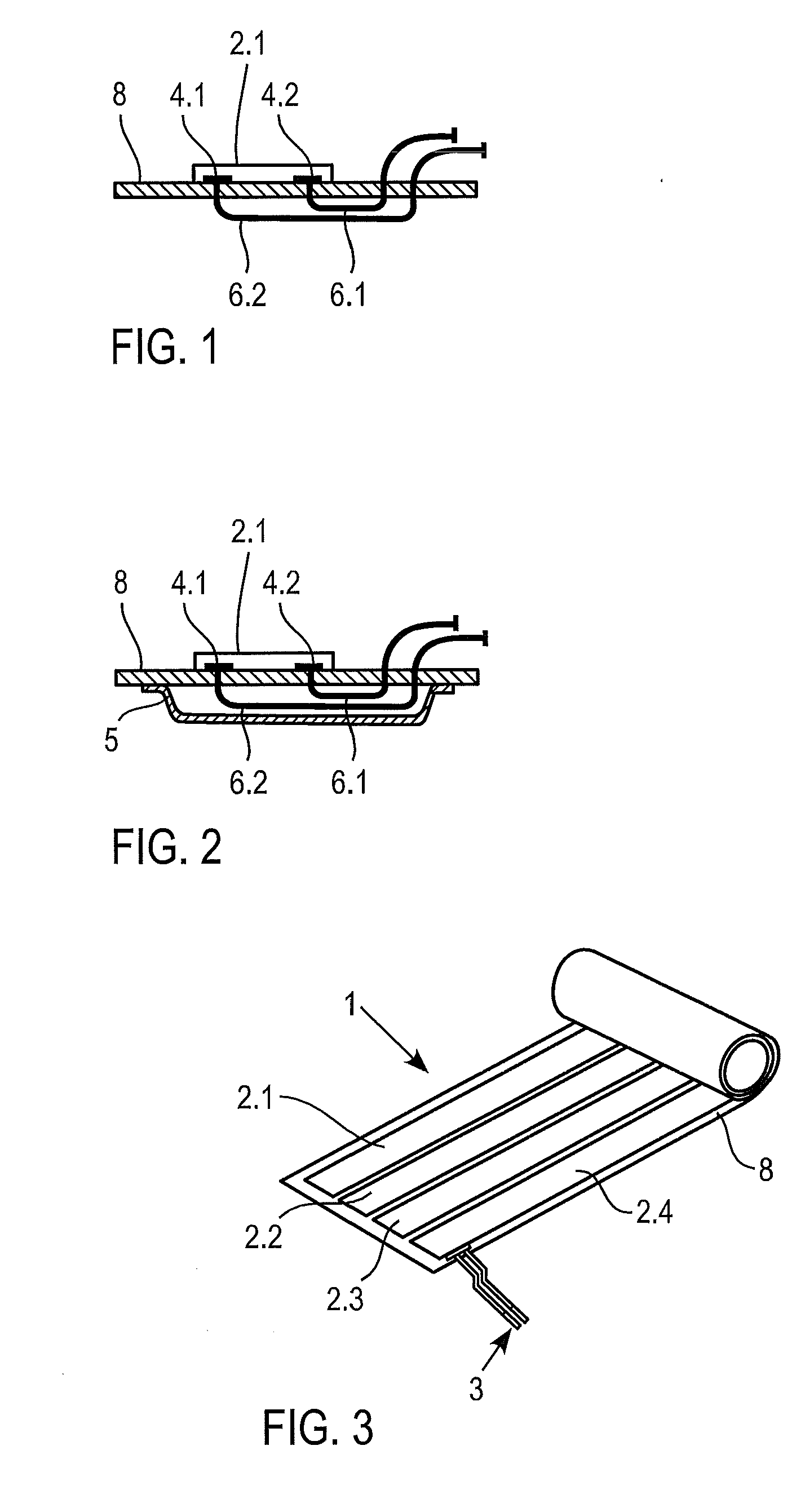
[0019]Contact points of a photovoltaic module are located on a side facing a sealing web and means of electrical connection pierce the sealing web.

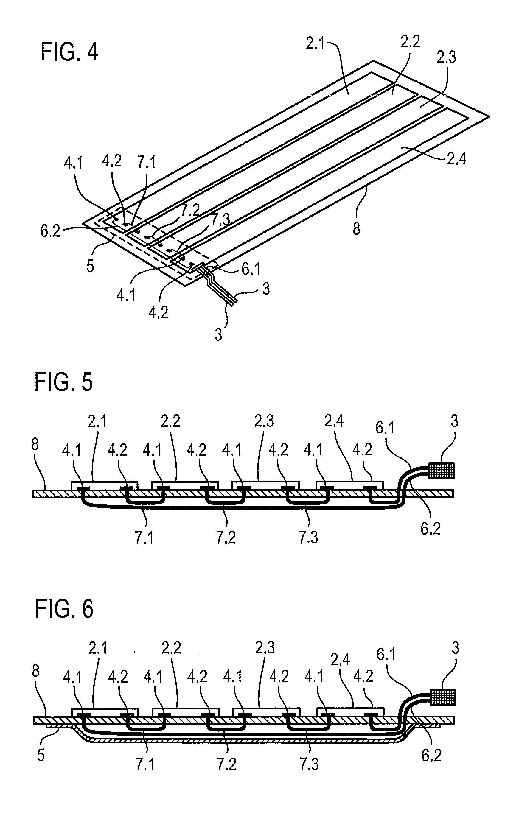
[0020]An exemplary development of the photovoltaic element calls for the means of electrical connection to the contact points to pierce the sealing web twice. In the case of several photovoltaic modules, an exemplary version of the photovoltaic element calls for the means of electrical connection of the contact points to pierce the sealing web twice between two contact points. For example, for the means of electrical connection can pierce the sealing web twice following the contact point on the photovoltaic module.

[0021]Provisions can be made for very reliable sealing by an additional covering web being applied along the piercing points in a region of the piercing points of the seal...


PUM


Abstract

The disclosure relates to a photovoltaic element having a sealing web with at least one photovoltaic module which is mounted on one side of the sealing web and has contact points and electrical connections. The contact points of the photovoltaic module can be arranged on a side facing the sealing web, and the electrical connections can pass through the sealing web.

Description

RELATED APPLICATIONS[0001]This application claims priority as a continuation application under 35 U.S.C. §120 to PCT / EP2009 / 059207, which was filed as an International Application on Jul. 17, 2009 designating the U.S., and which claims priority to European Application 08160613.9 filed in Europe on Jul. 17, 2008. The entire contents of these applications are hereby incorporated by reference in their entireties.FIELD[0002]The disclosure relates to photovoltaic elements.BACKGROUND INFORMATION[0003]Photovoltaic elements are known in general and have been mostly used for application to a roof surface. In this connection, several photovoltaic elements with their sealing webs are bonded next to one another so that the bonded photovoltaic elements provide a power generation function and, at the same time, perform the function of a roof seal.[0004]Fundamentally, single-layer and multi-layer photovoltaic systems can be distinguished. For a two-layer system, the upper layer performs the photov...

Claims


Application Information

Patent Timeline
IPC IPC(8): H01L31/02
CPCH01L31/02008H01L31/048H02S20/23Y02B10/12Y02E10/50H01L31/0504H02S30/20Y02B10/10
Inventor STREHLER, HANS-JAKOBHILLEBRAND HANSEN, WERNERJURISCH, RANDALLSCHUER, KLAUS
Owner SIKA TECH AG
Why Eureka
Try Eureka