Atomic magnetometer and magnetic sensing method

a magnetometer and magnetic sensing technology, applied in the direction of magnetic measurement, instruments, measurement devices, etc., can solve the problems of mixing noise, the condition concerning the amplification factor or noise of the individual photo-detector per se is not strictly uniform,

Active Publication Date: 2011-08-11
CANON KK
View PDF14 Cites 41 Cited by
  • Summary
  • Abstract
  • Description
  • Claims
  • Application Information

AI Technical Summary

Benefits of technology

[0024]According to the present invention, it is possible to provide a high-sensitivity sensor by directly measuring a difference between magnetic field intensities at different two positions as a difference in polarization rotation angle of the probe beam.

Problems solved by technology

However, actually, it is considered that a condition concerning an amplification factor or noise of an individual photo-detector per se is not strictly uniformized.
That is, when the magnetic field gradient information is intended to be obtained by using the electric signals obtained from the photo-detector, there is liability to mixing of noise, on the basis of characteristic difference between individual photo-detectors, in the magnetic field gradient information.

Method used


Image

  • Atomic magnetometer and magnetic sensing method
  • Atomic magnetometer and magnetic sensing method
  • Atomic magnetometer and magnetic sensing method

Examples


first embodiment

Method

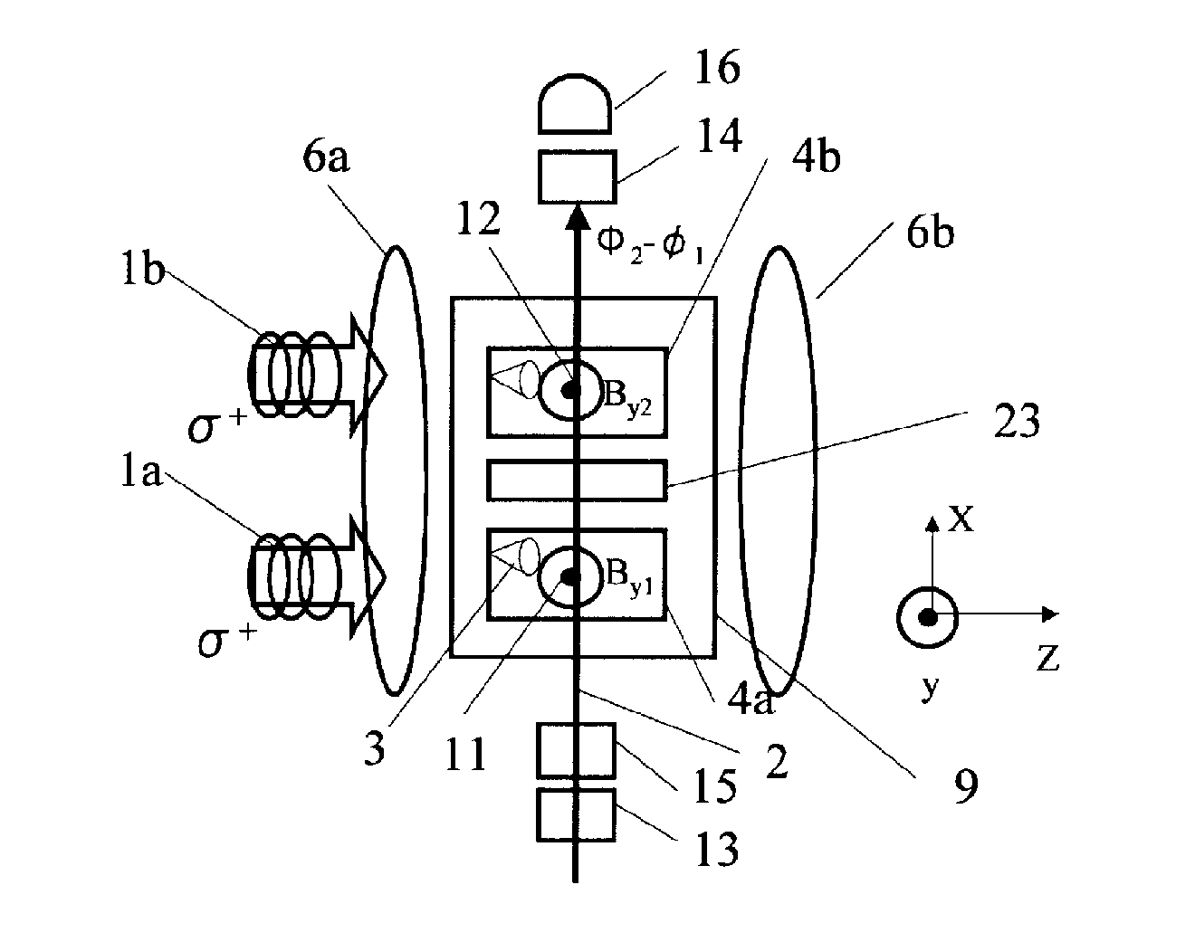
[0039]The magnetic sensing method according to the present invention in this embodiment will be described with reference to FIG. 1.

[0040]The magnetic sensing method in this embodiment has the following features.

[0041]That is, directions of spin of atoms constituting an atomic group contained in a hollow portion of a cell are uniformized by irradiating the atomic group with a pump beam. Then, the atomic group uniformized in spin direction of the atoms is irradiated with linearly polarized light as a probe beam to measure an angle of rotation of a plane of polarization of the probe beam, so that information on a measured magnetic field intensity is obtained.

[0042]In this embodiment, as shown in FIG. 1, first, a direction of polarization of the probe beam is rotated by a magnetic field intensity at a first measurement position (S1). Then, the probe beam with the rotated direction of polarization by the magnetic field intensity at the first measurement position is guided to a seco...

second embodiment

er

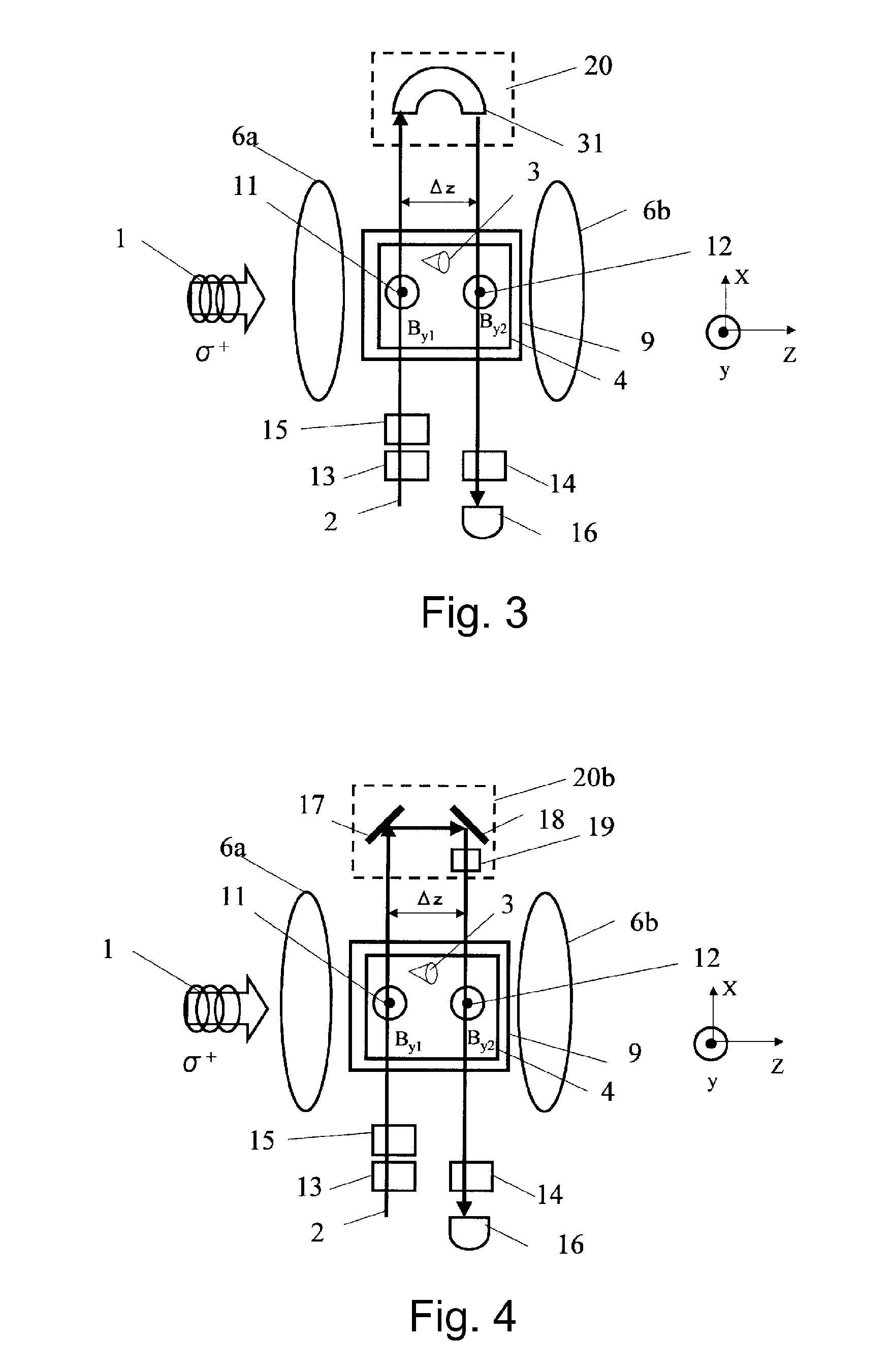
[0061]An atomic magnetometer in this embodiment has the following features.

[0062]Specifically, the atomic magnetometer includes a cell having a hollow portion, an atomic group contained in the hollow portion, and a pump beam light source for uniformizing directions of spin of a plurality of atoms constituting the atomic group. The atomic magnetometer further includes a probe beam light source for irradiating the cell with linearly polarized light as the probe beam, and a detector for detecting information on an angle of rotation of a plane of polarization of the linearly polarized light.

[0063]With respect to the atomic group in the cell, an irradiation direction of the circularly polarized light providing the pump beam and an irradiation direction of the probe beam are configured to intersect with each other at a first measurement position.

[0064]Then, with respect to the atomic group in the cell, an irradiation direction of the circularly polarized light providing the pump beam an...

third embodiment

[0073]The above-described First Embodiment and Second Embodiment are explained on the premise that the circularly polarized light is used as the pump beam but as shown below, the pump beam is not always required.

[0074]Specifically, a magnetometer in this embodiment is provided with a light source for a probe beam and a medium through which the probe beam is configured to propagate.

[0075]The medium is a substance which changes a polarization rotation angle depending on a magnetic field intensity at a first measurement position and a magnetic field intensity at a second measurement position and may specifically be vapor of alkali metal such as potassium or cesium. Further, rare gas (noble gas) such as helium or xenon may also be utilized. Further, it is also possible to employ substances, such as magnetic materials including Fe, Co, Ni, Y3Fe12, MnSb, MnBi, YFeO3, NdFe3, CrBr3, EuO, CdCv2S4, etc., and glass and the like. Further, a (magnetic field) gradiometer can also be realized by d...


PUM


Abstract

An atomic magnetometer includes a light source for a probe beam and a medium in which the probe beam is to be propagated. The medium is a substance which changes a polarization rotation angle of the probe beam depending on a magnetic field intensity at a first measurement position and a magnetic field intensity at a second measurement position different from the first measurement position. The atomic magnetometer directly measures a difference between the magnetic field intensity at the first measurement position and the magnetic field intensity at the second measurement position as a difference in polarization rotation angle, along a propagation path of the probe beam.

Description

TECHNICAL FIELD [0001]The present invention relates to a magnetometer for measuring a magnetic field intensity. Particularly, the present invention relates to an atomic magnetometer using alkali metal gas or rare gas and a magnetic sensing method.BACKGROUND ART [0002]A high-sensitivity atomic magnetometer using spin of alkali metal gas or rare gas has been proposed. U.S. Pat. No. 7,038,450 has proposed an atomic magnetometer in which a cell including an alkali metal vapor is irradiated with linearly polarized light (beam) from a linearly polarized light source for a pump beam and with circularly polarized light (beam) from a circularly polarized light source for a probe beam. Further, in order to measure a polarization rotation angle of the probe beam, a photo-diode array is used as a photo-detector.[0003]Incidentally, information on a magnetic field intensity (strength) depending on a measurement position is measured as magnetic field gradient information in some cases. In such cas...

Claims


Application Information

Patent Timeline
Patent Type & Authority Applications(United States)
IPC IPC(8): G01R33/02
CPCG01R33/022G01R33/26G01R33/032
Inventor SUGIOKA, HIDEYUKIICHIHARA, SUNAO
Owner CANON KK
Why Eureka
Try Eureka