
Liquid crystal display and method of driving the same

a technology of liquid crystal display and liquid crystal display, which is applied in the direction of electric digital data processing, instruments, computing, etc., can solve the problems of limited power consumption of portable devices, information may not be displayed, and limitations on reducing power consumption, so as to minimize power consumption

Inactive Publication Date: 2011-08-11
SAMSUNG DISPLAY CO LTD
View PDF8 Cites 22 Cited by
  • Summary
  • Abstract
  • Description
  • Claims
  • Application Information

AI Technical Summary

Benefits of technology

The present invention provides a liquid crystal display and a method of driving it that minimizes power consumption. The display includes transmission regions and reflection regions, with a smaller number of second sub pixels in the reflection regions. The method includes supplying second data signals to the second sub pixels when a power source is applied, displaying a predetermined image while supplying first data signals to the first sub pixels, and updating the still image while supplying the second data signals. The power source driving the first sub pixels is blocked in the standby mode, and the inversion rate of the second sub pixels is set to be no less than 2 Hz in the standby mode to further reduce power consumption.

Problems solved by technology

The capacity of a battery used as a power source in the portable apparatus is limited.
However, when a part of the liquid crystal is used, to display the still image enough information may not be displayed.
In addition, in order to display a still image in a standby mode, a driving voltage and driving signals are supplied to the liquid crystal panel, and thus, there are limitations on reducing power consumption.

Method used


Image

  • Liquid crystal display and method of driving the same
  • Liquid crystal display and method of driving the same
  • Liquid crystal display and method of driving the same

Examples


Embodiment Construction

[0025]Reference will now be made in detail to the present embodiments of the present invention, examples of which are illustrated in the accompanying drawings, wherein like reference numerals refer to the like elements throughout. The embodiments are described below in order to explain the present invention by referring to the figures.

[0026]It is to be understood that where is stated herein that a first element is said to be disposed or formed “on” or “in”, “connected to”, “coupled to” or “adjacent to”, a second element, the first element can directly contact the second element, or can be separated from the second element by one or more other elements located therebetween. In contrast, when an element is referred to as being disposed or formed “directly on” or “directly connected to” another element, there are no intervening elements present.

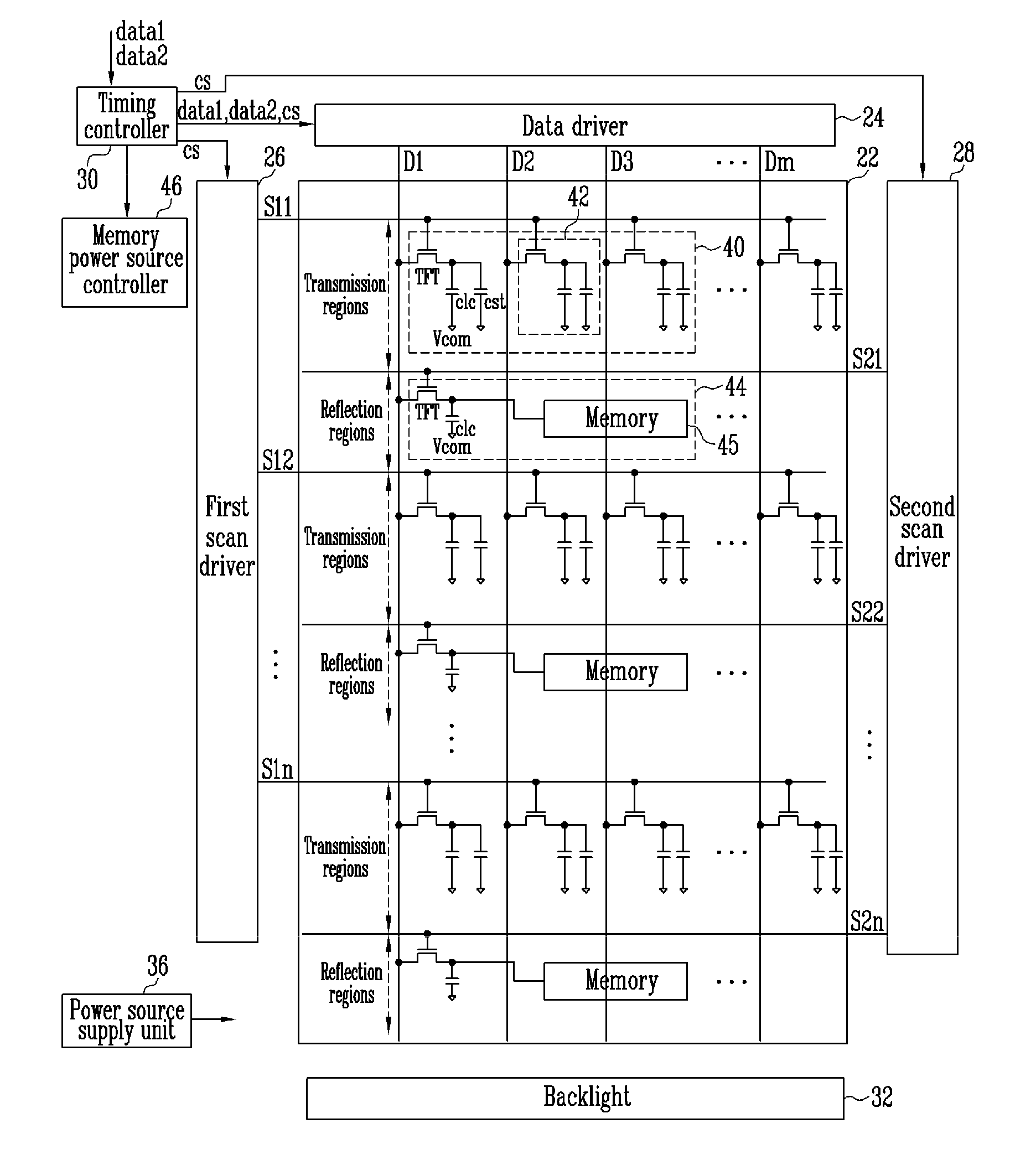
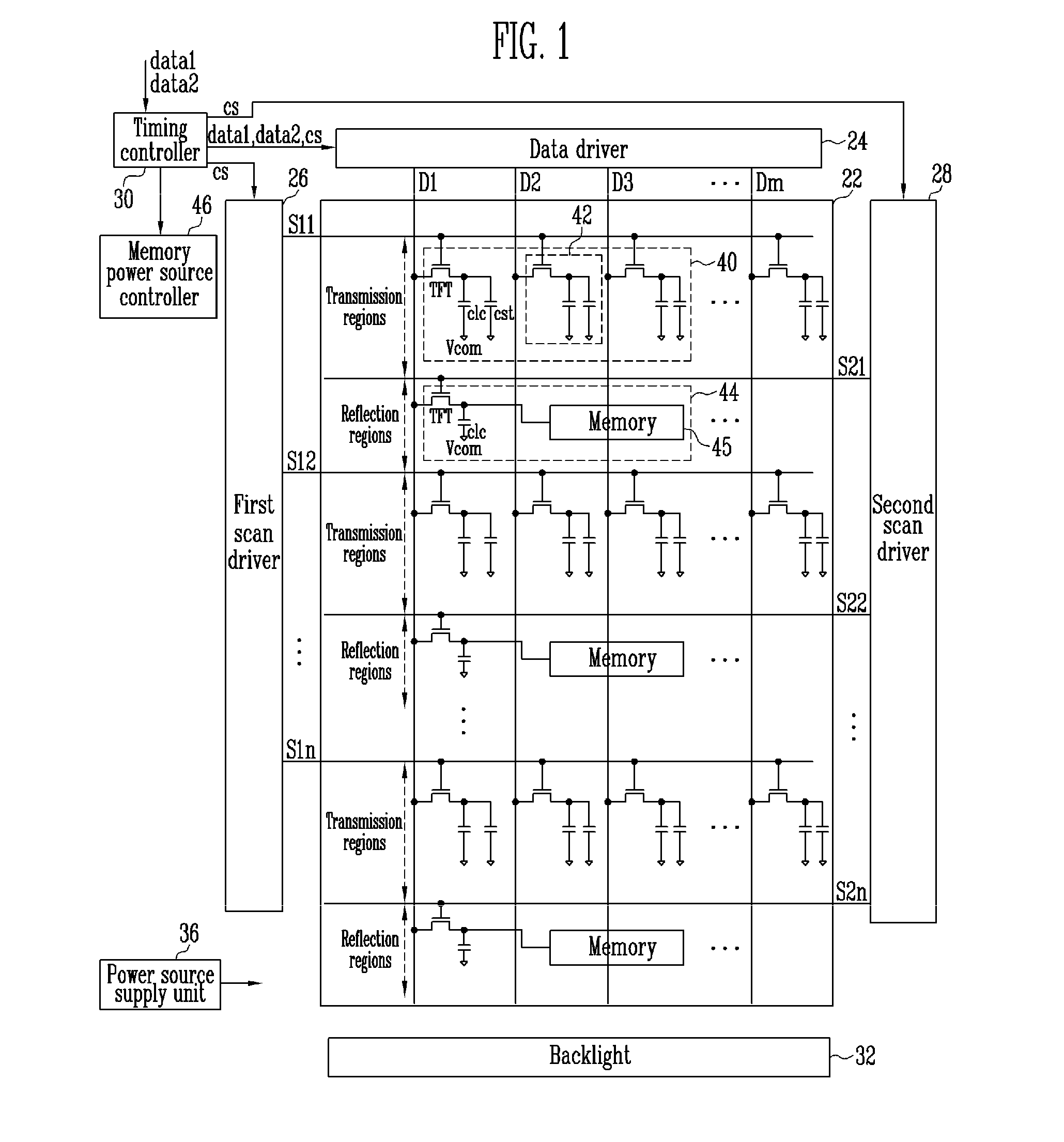
[0027]FIG. 1 is a view illustrating a liquid crystal display according to an embodiment of the present invention. Referring to FIG. 1, the liqu...


PUM

PropertyMeasurementUnit
inversion frequencyaaaaaaaaaa
voltageaaaaaaaaaa

Abstract

There is provided a liquid crystal display for minimizing power consumption. The liquid crystal display includes transmission regions formed in a liquid crystal panel in units of horizontal lines, reflection regions positioned between the transmission regions, first sub pixels formed in the transmission regions, and second sub pixels formed in the reflection regions. A total number of the second sub pixels is smaller than a total number of the first sub pixels.

Description

CROSS-REFERENCE TO RELATED APPLICATION[0001]This application claims the benefit of Korean Patent Application No. 10-2010-0012753, filed Feb. 11, 2010, in the Korean Intellectual Property Office, the disclosure of which is incorporated herein by reference.BACKGROUND[0002]1. Field[0003]Aspects of the present invention relate to a liquid crystal display and a method of driving the same, and more particularly, to a liquid crystal display for minimizing power consumption and a method of driving the same.[0004]2. Description of the Related Art[0005]A liquid crystal display controls light transmittance of liquid crystal cells in accordance with data signals to display an image. The liquid crystal display includes a liquid crystal panel having sub pixels arranged in a matrix and having a driving circuit driving the liquid crystal panel.[0006]The liquid crystal panel includes the sub pixels arranged at intersections between scan lines and data lines. Pixel electrodes and a common electrode a...

Claims


Application Information

Patent Timeline
Patent Type & Authority Applications(United States)
IPC IPC(8): G09G3/36G09G5/00G02F1/1347
CPCG02F1/133555G09G3/3648G09G3/3655G09G2330/022G09G2300/0456G09G2300/0842G09G2300/0857G09G2300/0443
Inventor LEE, MYUNG-WOOMOON, JUN-HEEKIM, CHEOL-MINKIM, SOON-DONG
Owner SAMSUNG DISPLAY CO LTD
Learn More