LED flashing annular ornament

an annular ornament and flashing technology, applied in the direction of lighting and heating apparatus, light support devices, bracelets, etc., can solve the problems of inconvenience to users, rapid exhaustion of batteries and unnecessary waste of electric energy, and inconvenient control of the control switch provided on the inner surface of the annular ornament, etc., to save power consumption, fashionable appearance, and convenient control

Inactive Publication Date: 2011-08-11
ASIA GLOBAL CORP
View PDF6 Cites 28 Cited by
  • Summary
  • Abstract
  • Description
  • Claims
  • Application Information

AI Technical Summary

Benefits of technology

[0005]A primary object of the present invention is to provide an LED flashing annular ornament, the LEDs of which can emit flashing light of different colors in a conveniently controllable manner, such as when the annular ornament is vibrated, so that the LED flashing annular ornament can save power consumption thereof while showing a fashionable appearance.

Problems solved by technology

The control switch provided on the inner surface of the annular ornament could not be conveniently operated when the annular ornament is worn on the user's hand.
The user, particularly a small child, often forgets to turn off the control switch to result in quickly exhausted batteries and unnecessary waste of electric energy.
Further, since the conventional LED flashing annular ornament requires frequent replacement of batteries thereof, it would no doubt bring inconveniences to the user.

Method used


Image

  • LED flashing annular ornament
  • LED flashing annular ornament
  • LED flashing annular ornament

Examples


Embodiment Construction

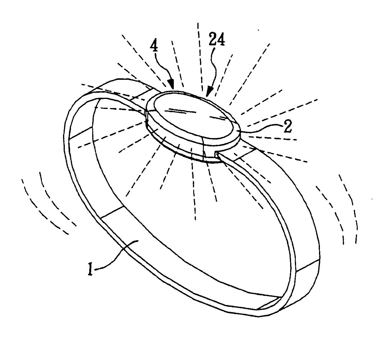
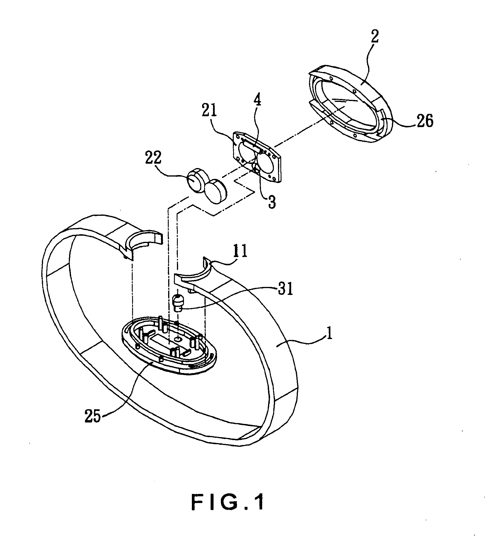
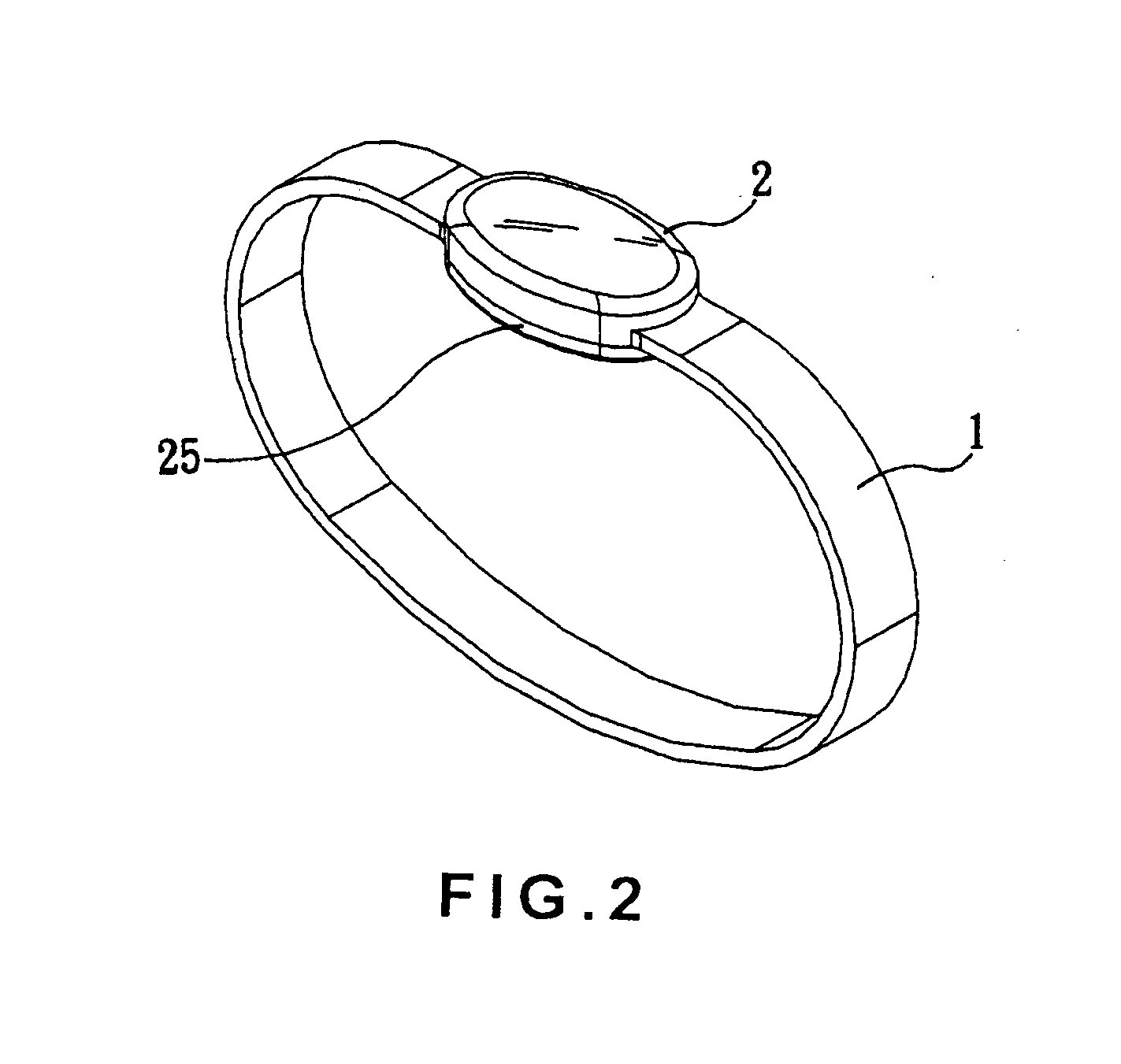
[0012]Please refer to FIGS. 1 and 2 that are exploded and assembled perspective views, respectively, of an LED flashing annular ornament according to a preferred embodiment of the present invention, and to FIG. 3 that is a circuit diagram of the LED flashing annular ornament of FIGS. 1 and 2.

[0013]As shown, in the preferred embodiment, the LED flashing annular ornament includes a band 1, an ornamental cover 2, a power switch 3, and a vibration switch 4 serving as a flash actuating switch. The band 1 has two facing but spaced ends for putting around a user's wrist or finger. The ornamental cover 2 has a light-transmitting top and defines an inner space for receiving a control circuit board 21 and batteries 22 therein. The control circuit board 21 has a control integrated circuit (IC) chip 23 and at least one LED 24 mounted thereon. The cover 2 is connected at two opposite ends to the two spaced facing ends of the band 1. A bottom cap 25 is connected to an open bottom side of the cove...


PUM


Abstract

An LED flashing annular ornament includes a band for putting around a user's wrist or finger; an ornamental cover connected to two facing ends of the band and having a control circuit board and batteries received therein, the control circuit board having a control IC chip and at least one LED provided thereon, and a bottom cap being connected to the ornamental cover to hold the band in place; a power switch arranged on the control circuit board and having an external button; and a vibration switch arranged on the control circuit board. When the external button is pushed to turn on the power switch, power is supplied from the batteries to the control IC chip; and when the user shakes the hand to vibrate the annular ornament while the power switch is on, the vibration switch is turned on and the control IC chip drives the LED to flash.

Description

FIELD OF THE INVENTION[0001]The present invention relates to an LED flashing annular ornament, and more particularly to an annular ornament having at least one LED that can be caused to flash in a conveniently controllable manner, such as when the annular ornament is vibrated.BACKGROUND OF THE INVENTION[0002]Generally, conventional glittering annular ornaments, such as bracelets or rings, are formed by designing different colors, styles, or patterns on outer surfaces of the annular ornaments, so that consumers can purchase the annular ornaments according to their preference. Alternatively, the conventional annular ornaments are provided with one or more light emitting diodes (LEDs) to emit light so as to highlight the beautiful appearance and colors thereof.[0003]The light emitting annular ornaments in the early stages are not provided with a flashing function. It is therefore tried by some manufacturers to develop an LED flashing annular ornament, so that the annular ornament not o...

Claims


Application Information

Patent Timeline
Patent Type & Authority Applications(United States)
IPC IPC(8): A44C5/00F21V21/08
CPCA44C15/0015A44C5/0007
Inventor AU, YING-YEE
Owner ASIA GLOBAL CORP
Why Eureka
Try Eureka