Bone Fixing Material and Thighbone Fixing System

a technology which is applied in the field of bone fixing material and thighbone fixing system, can solve the problems of easy falling out weak strength of threaded engagement of bone fixing material, so as to achieve the effect of appropriately preventing bone fixing material falling out of the thighbon

Inactive Publication Date: 2011-08-11
ROBERT REID INC
View PDF6 Cites 79 Cited by
  • Summary
  • Abstract
  • Description
  • Claims
  • Application Information

AI Technical Summary

Benefits of technology

[0027]According to the present invention, the bone fixing material attached and fixed to the intramedullary nail main body includes a form formed in a stick shape; and a cut out section forming section provided with at least one cut out section formed along a direction which crosses with a longitudinal direction of the bone fixing material and cut out from a surface to an inner side, wherein the bone fixing material is pressed into an inner side of each of the one bone piece portion and the other bone piece portion composing the thighbone so that the cut out section forming section is positioned in a deeper side than the bone fracture line. Therefore, the cancellous bone surrounding the bone fixing material is in a state in the inner side of the cut out section after surgery, and even if the bone fixing material is moved in the axis direction, the cut out section is easily caught by the cancellous bone. Consequently, the bone fixing material can be made so that it does not easily fall out from the thighbone. Moreover, with the cut out section, the surface area of the bone fixing material can be made larger, and therefore can be appropriately supported by the pressure from the cancellous bone surrounding the bone fixing material in a state pressed in the inner side of the one bone piece portion and the other bone piece portion.
[0028]Therefore, the bone fixing material falling out from the thighbone can be appropriately prevented.

Problems solved by technology

However, since the cancellous bone mass decreases due to forming the pilot hole, there is a possibility that a problem occurs, such as the strength of the threaded engagement of the bone fixing material is weak even if the bone fixing material is screwed in.
Specifically, in those with small cancellous bone mass such as those who have weak bones or those who are aged, there is a possibility that the strength of the threaded engagement of the bone fixing material becomes weak.
However, since the blade type bone fixing material is supported by pressure from the surrounding cancellous bone, when the cancellous bone mass is small, there is a problem that the bone fixing material falls out easily as in the screw type bone fixing material.

Method used


Image

  • Bone Fixing Material and Thighbone Fixing System
  • Bone Fixing Material and Thighbone Fixing System
  • Bone Fixing Material and Thighbone Fixing System

Examples


Embodiment Construction

[0039]Below, a specific embodiment of the present invention is described with reference to the drawings. However, the scope of the invention is not limited to the illustrated examples.

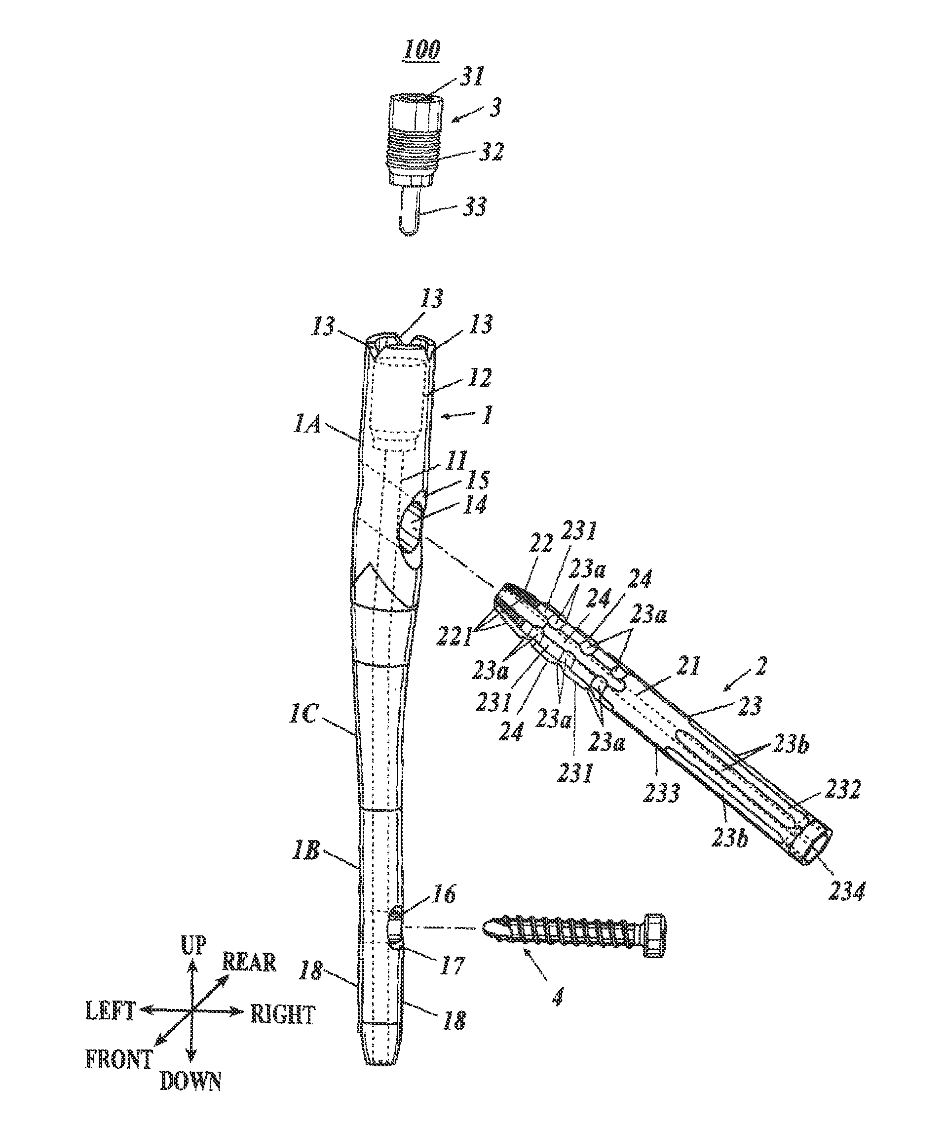
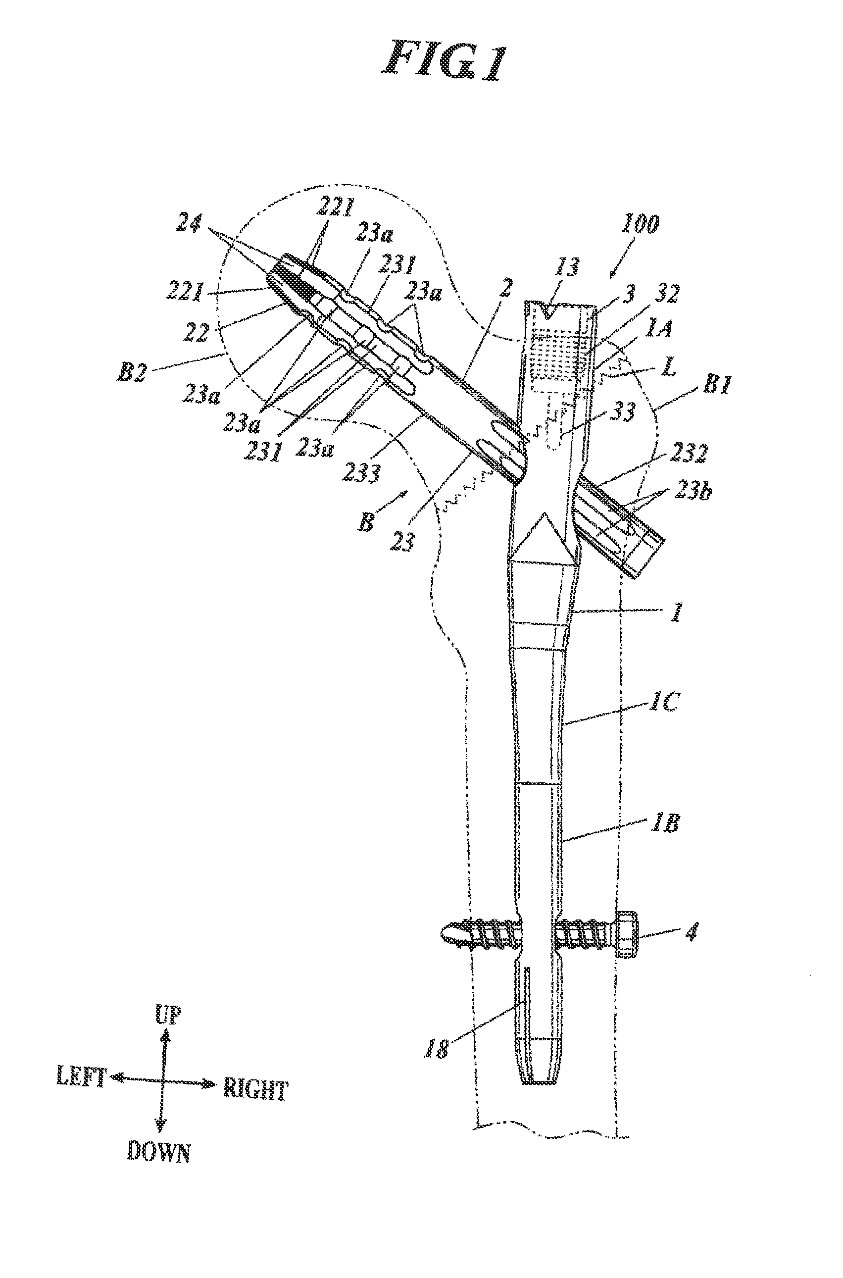
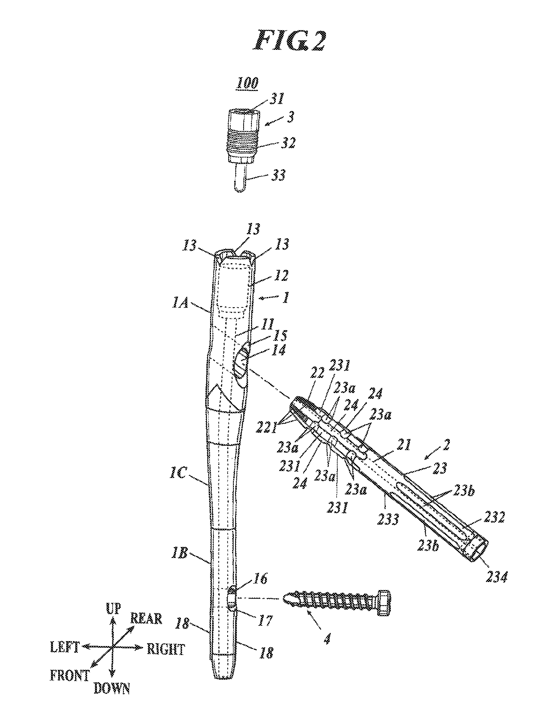
[0040]FIG. 1 is a diagram schematically showing a state of a thighbone fixing system 100 attached to a thighbone B illustrated as a preferable embodiment employing the present invention viewed from a front side and FIG. 2 is an exploded perspective view of the thighbone fixing system 100.

[0041]In the description described below, when the thighbone fixing system 100 is attached to the thighbone B, a proximal end side of the thighbone B is the upper side and a distal end side of the thighbone B is the lower side, a bone head side of the thighbone B is the left (inner) side and the opposite side of the bone head is the right (outer) side, and the stomach side is the front side and the back side is the rear side.

[0042]As shown in FIG. 1, the thighbone fixing system 100 of the present embodiment is attached...


PUM


Abstract

A bone fixing blade (2), which is fixed at a intermedullary nail main body (1) to be inserted into a medullary space of a fractured thighbone and which fixes a big bone piece portion (B1) and a small bone piece portion (B2) composing the thighbone, is provided with a cut-out portion forming unit (231) formed in a stick-like shape along a circumferential direction of the bone fixing blade comprised of three cut-out portions (23a) cut out from the surface toward the inside, wherein the cut-out portion forming unit (231) is pressed into the inside of each of the big bone piece portion and the small bone piece portion to be in a position on a recess side that is deeper than a bone fracture line (L).

Description

TECHNICAL FIELD [0001]The present invention relates to a bone fixing material and a thighbone fixing system to fix a fractured thighbone.BACKGROUND ART [0002]Conventionally, there is known a thighbone fixing system to treat a fracture of a proximal end of the thighbone such as a thighbone neck portion (for example, see Patent Documents 1 and 2).[0003]Specifically, the thighbone fixing system includes an intramedullary nail main body to be inserted to a medullary space of a thighbone from a proximal end of the thighbone; a bone fixing material to be inserted through an inserting hole formed so as to cross with a longitudinal direction of the intramedullary nail main body and the bone fixing material is positioned so that a tip section is positioned in the bone head of the thighbone; and a fixing screw to fix the bone fixing material inserted through the inserting hole so as not to rotate.[0004]As a bone fixing material, for example, there is known a screw type which is screwed into t...

Claims


Application Information

Patent Timeline
Patent Type & Authority Applications(United States)
IPC IPC(8): A61B17/58
CPCA61B17/744
Inventor MURASE, TAKAHIRO
Owner ROBERT REID INC
Why Eureka
Try Eureka