Unlimited Downhole Fracture Zone System

a fracture zone and unlimited technology, applied in the direction of fluid removal, borehole/well accessories, construction, etc., can solve the problems of limited number of unique seats, reduced production from the lower zone, and open up the possibility of mis-ordering the balls, so as to increase production and accidental isolation of the fracture zone

Inactive Publication Date: 2011-08-18
TEAM OIL TOOLS LP
View PDF71 Cites 36 Cited by
  • Summary
  • Abstract
  • Description
  • Claims
  • Application Information

AI Technical Summary

Benefits of technology

[0009]The invention overcomes many of the above noted deficiencies with the prior art. A single size ball is employed which allows for a larger diameter production tube to be employed. This increases production compared to the prior art which requires sequentially smaller diameter balls and tubing. Since all the balls are of the same size, the possibility of mis-ordering the ball

Problems solved by technology

The use of sequentially smaller ball seats on sleeves within the well results in a limited number of unique seats for a given tubing size and in a limited number of unique zones for a fracture project.
This results in reduced production from the lower zones and fre

Method used


Image

  • Unlimited Downhole Fracture Zone System
  • Unlimited Downhole Fracture Zone System
  • Unlimited Downhole Fracture Zone System

Examples


Embodiment Construction

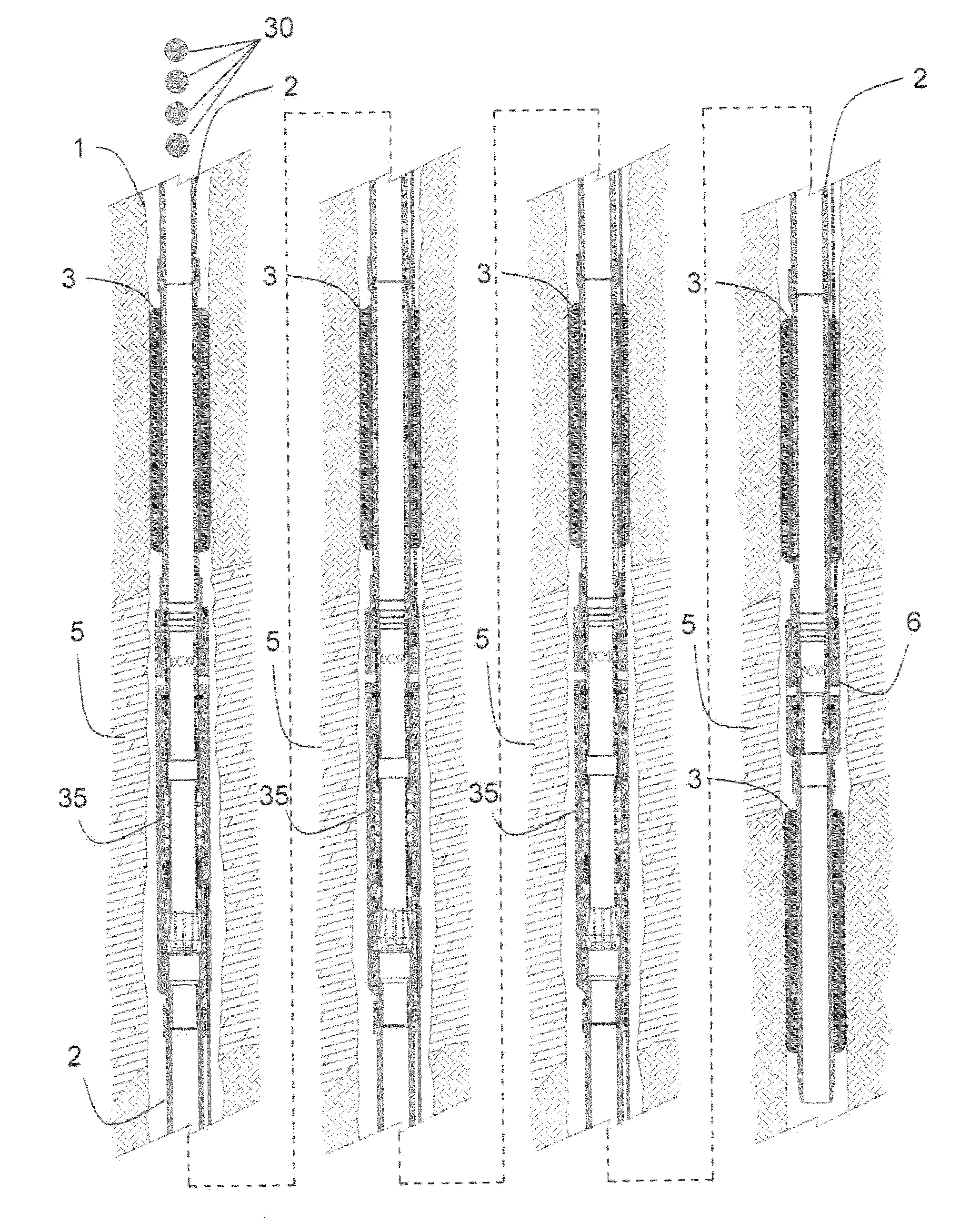
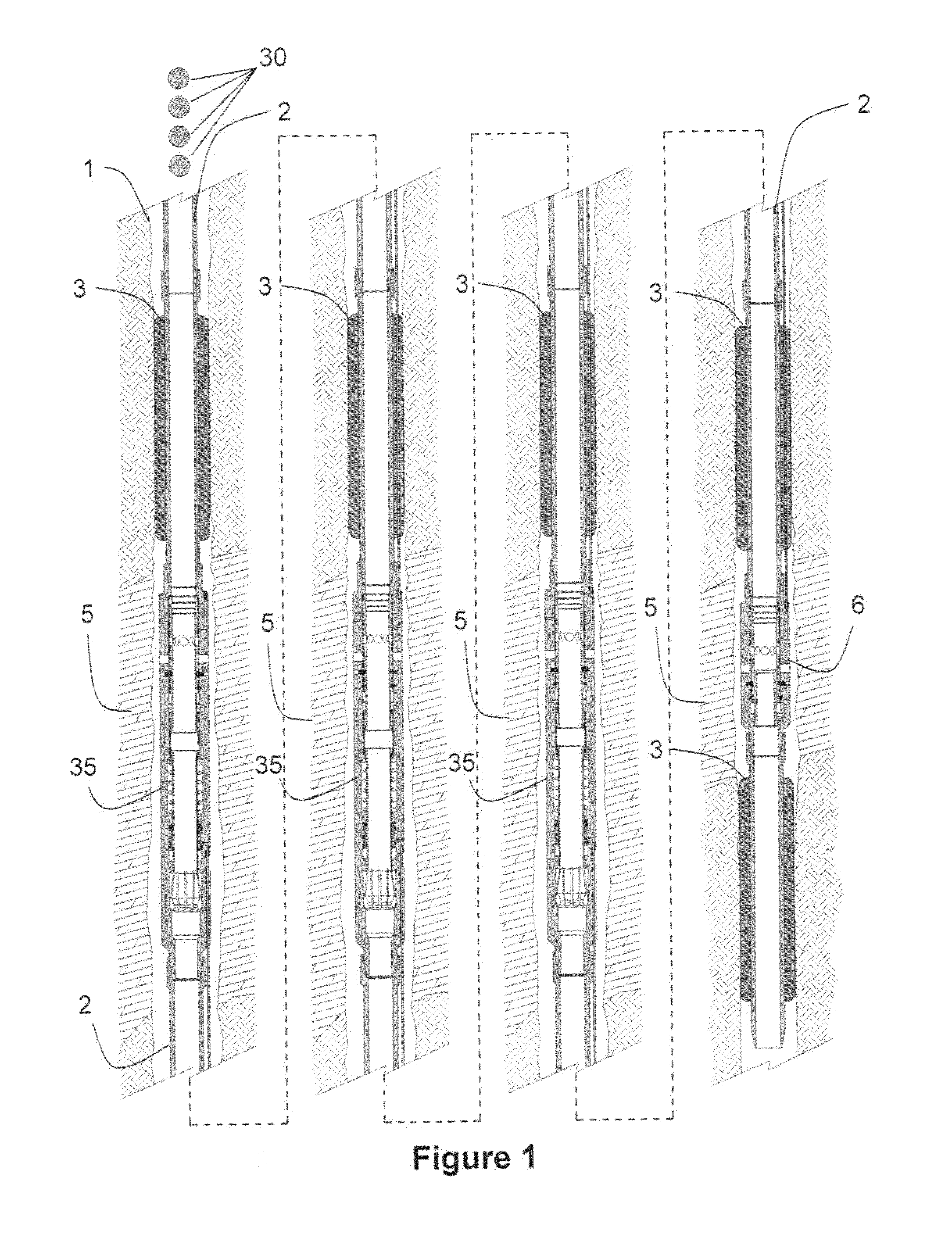
[0022]FIG. 1 illustrates an embodiment of the system deployed within a well bore 1. The system includes tubing 2, packers 3, a plurality of diverter valves 35, and lower initiation tool 6. Lower initiation tool 6 and diverter valves 35 are positioned within zones 5 using suitable tubing 2. Zones to be treated (called “fracturing zones” herein) 5 are isolated by positioning known packers 3 above and below the diverter valves and the lower initiation tool. Fracturing zones 5 are illustrated as separated by non-productive segments in the figure, which would apply in a vertical well or wellbore at an angle that penetrates both productive and non-productive zones. In a horizontal portion of a well, the non-productive zones may not be present.

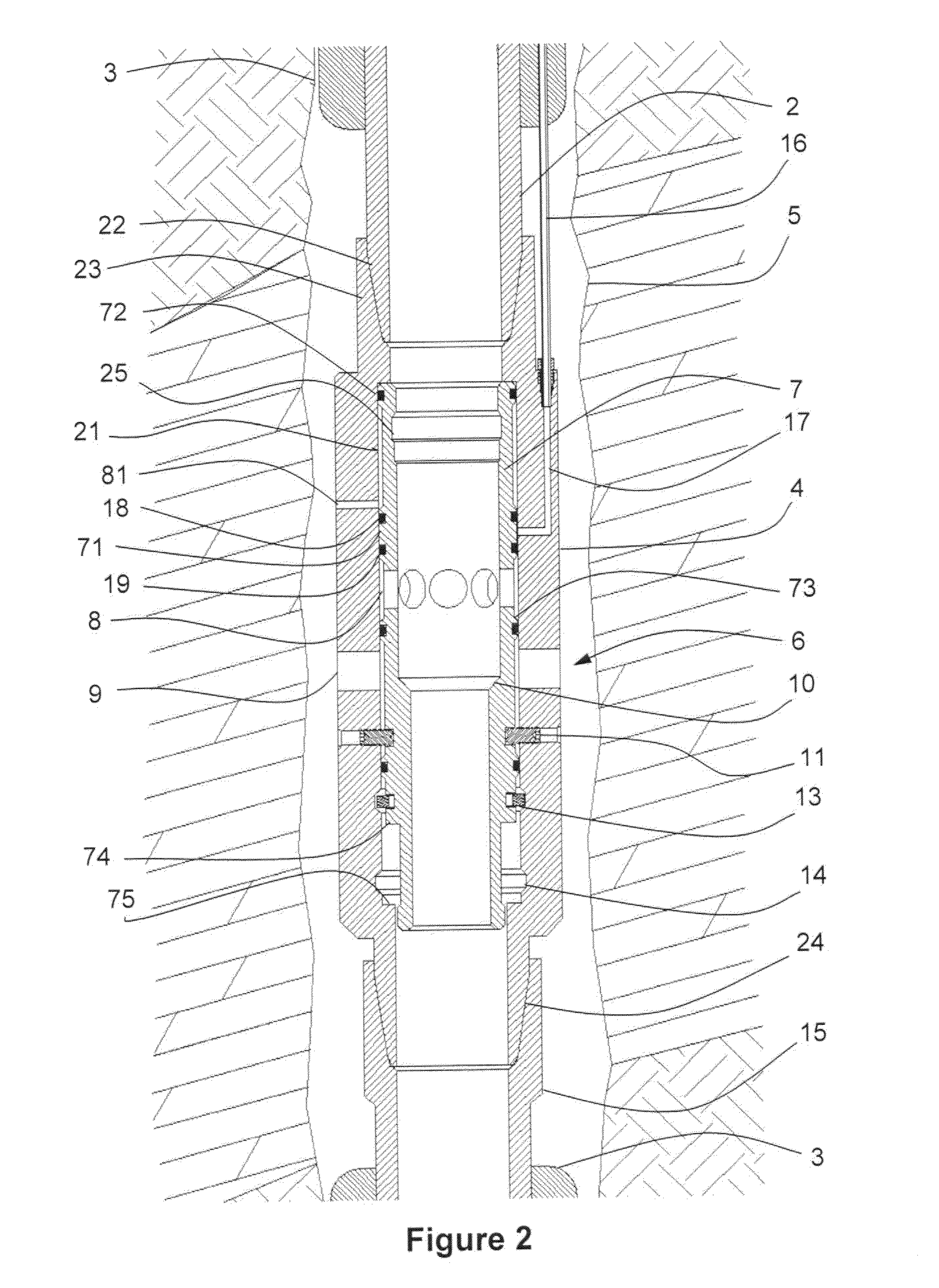
[0023]Referring to FIG. 2, the lower initiation tool 6 includes a housing 4, which at its lower end 24 is adapted for connection to tubing 15 by any suitable means such as screw threads. The upper portion of the housing 23 is similarly adapted for at...


PUM


Abstract

Apparatus and method are provided for diverting treatment fluids in wells. Sliding sleeves or valves are sequentially opened by dropping balls that may be of uniform size. Opening of one valve moves a collet into position such that the same size ball can be used to open a second valve. Any selected number of valves can be opened with the same size balls. Systems using the valves are also disclosed, along with methods for operating.

Description

BACKGROUND OF INVENTION[0001]1. Field of the Invention[0002]This invention pertains to a system for injecting treatment fluids into a selected isolated interval in an oil and gas well. More particularly, valves disposed along a tubular are opened sequentially by pumping balls of one size down the tubular, causing one valve to open and another valve mechanism to be moved into position to be opened by a following ball.[0003]2. Description of Related Art[0004]Treatment fluids, such as hydraulic fracturing or acidizing fluids, are often used to treat multiple zones or segments of the earth penetrated by a wellbore. It is usually preferable to treat each zone or segment individually and to divert the treating fluid to another zone or segment when a designed amount of treating fluid has been injected into a zone or segment. In vertical wells, different zones of a producing formation are normally treated individually. In the horizontal wellbore portion of “horizontal wells,” different segm...

Claims


Application Information

Patent Timeline
IPC IPC(8): E21B34/06E21B34/00E21B33/12
CPCE21B34/14E21B2034/007E21B43/26E21B2200/06E21B34/142
Inventor MAILAND, JASON C.WHITE, DEMETRI M.
Owner TEAM OIL TOOLS LP
Why Eureka
Try Eureka