Millimeter wave surface imaging radar system

a radar system and millimeter wave technology, applied in the field of radar systems, can solve the problems of significant hazard to the safety of air traffic, large distances of radiation at these millimeter wave wavelengths, and loss of human life, and achieve reliable and effective fod detection and large scan coverage

a radar system and millimeter wave technology, applied in the field of radar systems, can solve the problems of significant hazard to the safety of air traffic, large distances of radiation at these millimeter wave wavelengths, and loss of human life, and achieve reliable and effective fod detection and large scan coverage

US20110199254A1Inactive Publication Date: 2011-08-18TREX AVIATION

Image

  • Millimeter wave surface imaging radar system
  • Millimeter wave surface imaging radar system
  • Millimeter wave surface imaging radar system

Examples


first preferred embodiment

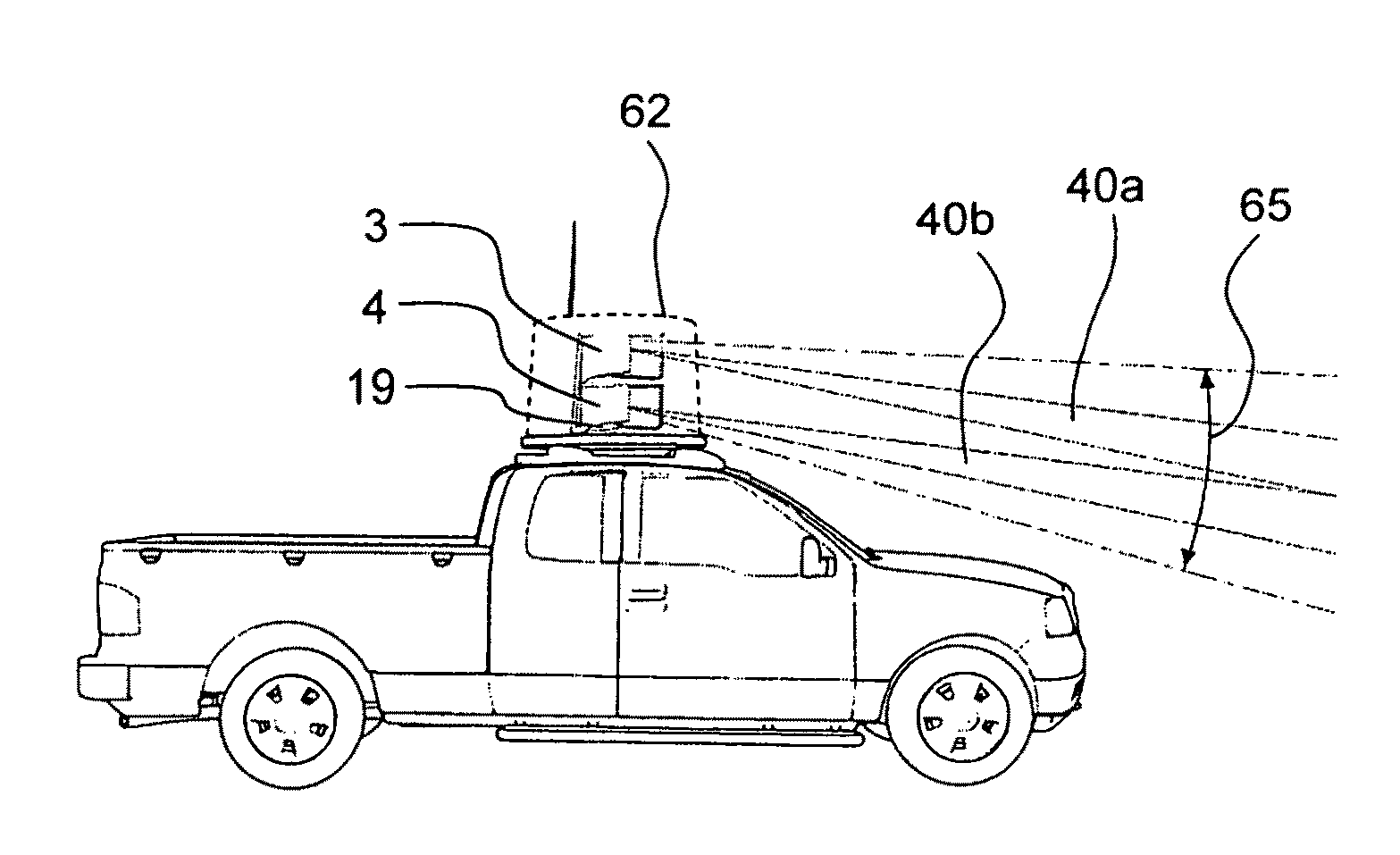
[0034]The preferred embodiment of the present invention is described in FIGS. 1 through 9. This embodiment is a three dimensional W-band Frequency Modulated Continuous Wave (FMCW) active imaging radar system. The system is capable of accurately determining the bearing and range to foreign objects on the airport surfaces and displaying this information to system operators. The system has up to 200 meters (600 feet) operation range and has to be driven around in order to detect FOD in larger areas.

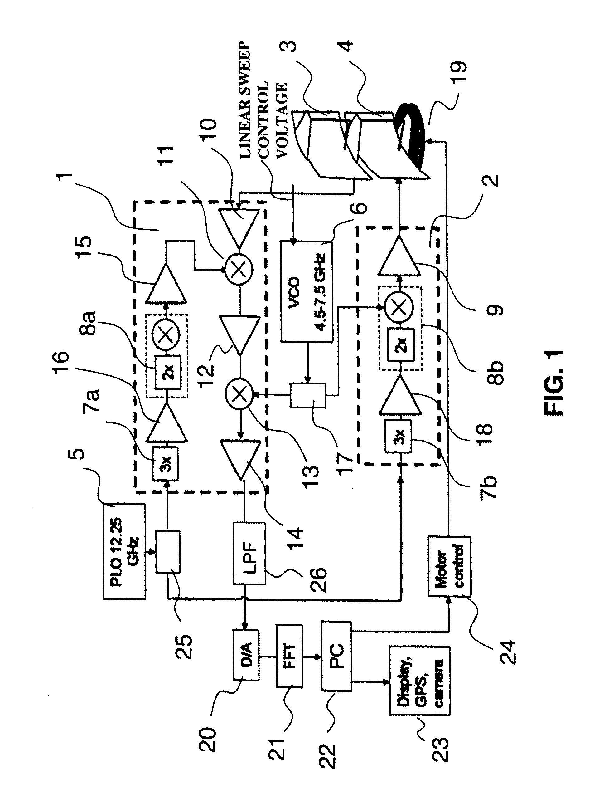
[0035]The radar of the system consists of a millimeter wave transmitter, receiver, one each transmit and receive prime focus reflector antennas, receiver signal digitizer and FFT processor. The transmit antenna and the receive antenna have similar configurations. They form narrow co-aligned / overlapping beams which are 0.85 degree wide (spreading from several inches in the near field) in the vertical directions and 0.34 degree wide (spreading from about two feet in the near field) in the hori...


PUM


Abstract

A short range millimeter wave surface imaging radar system. The system includes electronics adapted to produce millimeter wave radiation scanned over a frequency range of a few gigahertz. The scanned millimeter wave radiation is broadcast through a frequency scanned transmit antenna to produce a narrow transmit beam in a first scanned direction (such as the vertical direction) corresponding to the scanned millimeter wave frequencies. The transmit antenna is scanned to transmit beam in a second direction perpendicular to the first scanned direction (such as the horizontal or the azimuthal direction) so as to define a two-dimensional field of view. Reflected millimeter wave radiation is collected in a receive frequency scanned antenna co-located (or approximately co-located) with the transmit antenna and adapted to produce a narrow receive beam approximately co-directed in the same directions as the transmitted beam in approximately the same field of view. Computer processor equipment compares the intensity of the receive millimeter radar signals for a pre-determined set of ranges and known directions of the transmit and receive beams as a function of time to produce a radar image of at least a desired portion of the field of view. In preferred embodiment the invention is mounted on a truck and adapted as a FOD finder system to detect and locate FOD on airport surfaces.

Description

CROSS REFERENCE TO RELATED APPLICATIONS[0001]This application is a continuation-in-part of Ser. No. 12 / 286,981, filed Oct. 3, 2008, Mobile Millimeter Wave Imaging System.FIELD OF THE INVENTION[0002]The present invention relates to radar systems and in particular to millimeter wave imaging radar systems.BACKGROUND OF THE INVENTIONImaging with Millimeter Waves[0003]Passive and active imaging systems operating at millimeter wavelengths (1 cm to 1 mm; 30 GHz to 300 GHz) are well known. Short wave length at mm-wave frequencies allows narrow beams to be created with relative small antennas and to produce high resolution passive and active images. Objects in the image can be accurately located due to the narrow beams and, when the systems operate in the radar mode, a high sensitivity for reflected signals can be achieved. An important quality of millimeter wave systems is that they are relatively little attenuated by substantial distances of fog or smoke compared to visible light. Radiatio...

Claims


Application Information

Patent Timeline
18 Aug 2011
Publication
US20110199254A1
IPC
G01S13/06
CPC
G01S13/345; G01S13/426; G01S13/89; G01S13/867; H01Q19/175; H01Q21/0043; G01S2013/916
Inventors
BISHOP, GRANT; LOVBERG, JOHN A.