Inkjet print engine having a plurality of laser scanning units

a laser scanning unit and printing engine technology, applied in the field of printing, can solve the problems of affecting the printing quality of neighboring dots in the main scanning direction, limiting the printing quality, and affecting the printing quality, so as to reduce the scanning speed, minimize shock wave interference, and avoid shock wave interference between the different laser beam spot positions

Inactive Publication Date: 2011-08-18
OCE TECH
View PDF10 Cites 3 Cited by
  • Summary
  • Abstract
  • Description
  • Claims
  • Application Information

AI Technical Summary

Benefits of technology

[0022]In one embodiment, the laser beam spot positions are remote from each other in the main scanning direction. Thus, because the full width of the ink support in the main scanning direction is available for distributing the laser beam spot positions, a large distance between each two laser beam spot positions is possible. Thus, shock wave interference between the different laser beam spot positions is avoided.
[0023]In one embodiment, the laser beam spot positions are remote from each other in the sub scanning direction, i.e. perpendicular to the main scanning direction. For example, the laser scanning units scan the ink support in an interlaced arrangement. Interlaced scanning allows a reduction of the scanning speed in order to minimize shock wave interference, because a plurality of scan lines is scanned simultaneously.
[0024]In one embodiment, the printing engine further comprises a modulating unit configured to modulate an intensity of each laser beam corresponding to image information supplied to the printing engine, and image information corresponding to one line to be printed in the main scanning direction is shared between the laser scanning units. The modulating unit modulates an intensity of each laser beam corresponding to scan operations of the laser scanning units and corresponding to image information supplied to the printing engine. Because the image information is shared between the scanning units, it is not required that one laser beam scans the entire width of the ink support in the main scanning direction in order to print one line of image information. Thus, the scanning speed can be reduced while maintaining a high printing speed in the sub scanning direction, i.e. perpendicular to the main scanning direction.
[0025]In one embodiment, the ink support is divided into scanning sections in the main scanning direction, and each laser scanning unit is associated with one of the scanning sections, and each laser scanning unit is adapted to scan an associated scanning section of the ink support in substantially the main scanning direction. Thus, the scanning operation of each laser scanning unit is restricted to substantially the associated scanning section of the ink support. However, synchronization and focus control measures may require an actual scanning operation to be performed outside the scanning sections. By dividing the ink support into scanning sections in the main scanning direction, the scanning length of each laser scanning unit is reduced as compared to the total scanning length of the ink support in the main scanning direction (corresponding to the width of the ink support). Thus, the length of the path of light can be significantly reduced. For example, if a single laser beam was used to scan a 320 mm wide area of the ink support, the maximum length of a path of light would typically be around 400 †mm. By dividing the ink support, for example, into 10 scanning sections, the maximum length of the path of light may be reduced to 40 mm. This facilitates the focusing of the laser beams into small beam spots with small sized, low cost optics.
[0026]In one embodiment, the laser scanning units are arranged in a line in the main scanning direction. For example, the positions of the laser scanning units may correspond to the positions of the scanning sections described above. Arranging the laser scanning units in the main scanning direction facilitates sharing image information corresponding to one line to be printed in the main scanning direction between the laser scanning units.
[0027]Preferably, the directing unit of each laser scanning unit comprises at least one movable mirror surface for deflecting the laser beam. For example, a rotatable polygon mirror may be used having, for example, 8 mirror surfaces. When each laser scanning unit comprises at least one movable mirror surface for deflecting the laser beam, this simplifies the light path of each laser scanning unit and, thus, facilitates focus control, as compared to a structure where several laser beams would share one rotatable polygon mirror.

Problems solved by technology

The inventor has determined that in a conventional method of printing, wherein a printing substance is transferred from a color support onto a printing substrate, and wherein the printing substance undergoes a volume and / or position change by means of heating using a laser beam, the printing quality is limited by the nature of the process.
Due to this, the printing of neighboring dots in the main scanning direction is disturbed.
This limits the printing quality.

Method used


Image

  • Inkjet print engine having a plurality of laser scanning units
  • Inkjet print engine having a plurality of laser scanning units
  • Inkjet print engine having a plurality of laser scanning units

Examples


Embodiment Construction

[0049]The present invention will now be described with reference to the accompanying drawings, wherein the same reference numerals have been used to identify the same or similar elements throughout the several views.

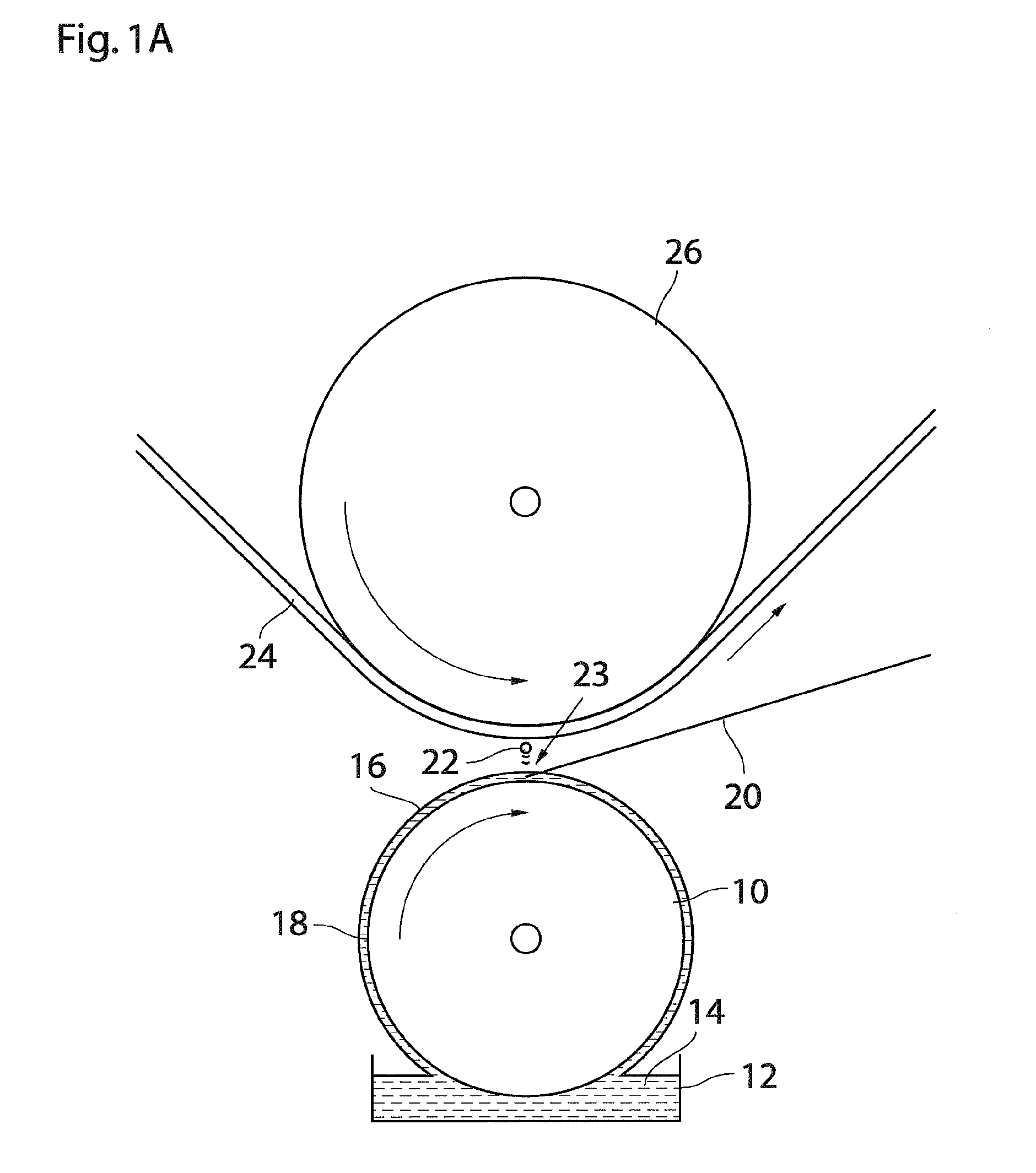
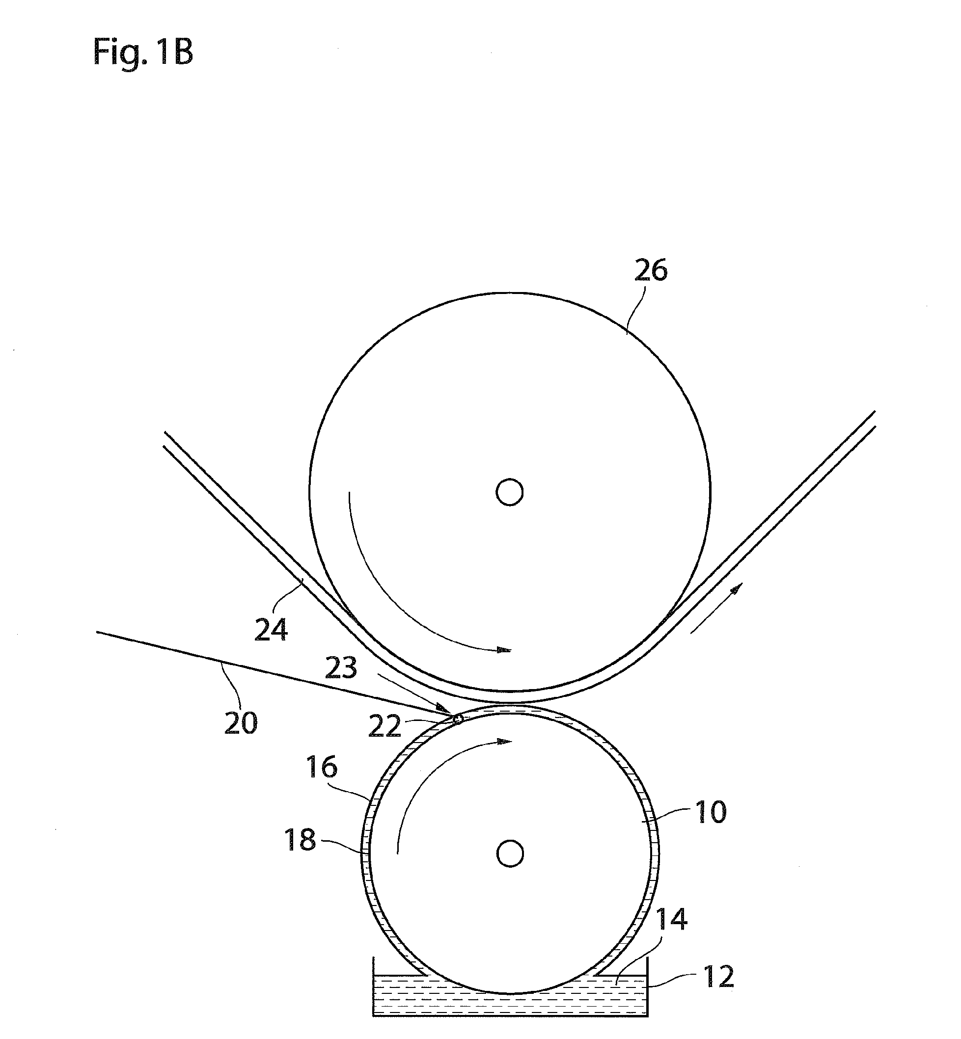
[0050]FIG. 1A schematically shows a cylindrical ink support 10 of a printing engine, which is rotatable about its axis as indicated by an arrow. An ink supply 12 is adapted to supply ink 14 to the ink support 10, thereby forming a homogeneous and continuous amount of ink 16 on a cylindrical outer surface 18 of the ink support 10. The ink 14 is, for example, flexographic or rotogravure ink.

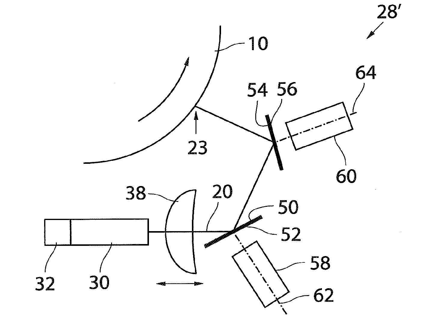
[0051]A surface 18 of the ink support 10 is scanned by a plurality of laser beams, of which one laser beam 20 is shown in FIG. 1A, in substantially a main scanning direction which is perpendicular to the plane of view in FIG. 1A. When the laser beam 20 hits the ink support 10 at a higher power level, ink is locally heated or vaporized, and a jet 22 of ink is created at the laser beam sp...


PUM


Abstract

A printing engine, having an ink support adapted to support an amount of ink, a plurality of laser scanning units, each laser scanning unit including a laser adapted to emit a laser beam and a directing unit configured to direct the laser beam onto the ink support. The laser scanning unit is adapted to apply energy to the amount of ink at a laser beam spot position. The laser scanning units are adapted to simultaneously scan the ink support substantially in a main scanning direction with respective laser beam spot positions, the laser beam spot positions being remote from each other.

Description

CROSS-REFERENCE TO RELATED APPLICATIONS[0001]This application is a Continuation of International Application No. PCT / EP2009 / 063893, filed on Oct. 22, 2009, and for which priority is claimed under 35 U.S.C. §120, and which claims priority under 35 U.S.C. §119 to Application No. 08168024.1, filed on Oct. 31, 2008. The entirety of each of the above-identified applications is expressly incorporated herein by reference.BACKGROUND OF THE INVENTION[0002]1. Field of the Invention[0003]The present invention relates to the field of printing using laser light to apply energy to an amount of ink at a laser beam spot position. More specifically, the present invention relates to a printing engine and a printing method for applying energy to an amount of ink at a laser beam spot position.[0004]2. Background of the Invention[0005]WO 01 / 72518 A1 discloses a printing method for the transfer of a printing substance from a color support onto a printing substrate; wherein the printing substance undergoe...

Claims


Application Information

Patent Timeline
Patent Type & Authority Applications(United States)
IPC IPC(8): B41J2/47
CPCB41J2/473H04N1/192H04N1/1135G02B26/12
Inventor HEEREN, THEODORUS A.G.
Owner OCE TECH
Why Eureka
Try Eureka