Scanning Touch Systems

a touch system and touch technology, applied in the direction of instruments, electric digital data processing, input/output processes of data processing, etc., can solve the problem that the rotating nature of the scanning beam would require a very long detector, and achieve the effect of reducing the average optical output, improving performance, and reducing the speed of scanning

Inactive Publication Date: 2015-07-30
LIGHT BLUE OPTICS
View PDF3 Cites 17 Cited by
  • Summary
  • Abstract
  • Description
  • Claims
  • Application Information

AI Technical Summary

Benefits of technology

[0026]In embodiments the touch sensing system may be provided with a power and / or safety control system to reduce an average optical output from the laser when a speed of the scanning is reduced. Thus, for example, the system may default to only switching the laser on, or up to its usual operating power, when scanning at full operating speed.
[0027]In embodiments the touch sensing system pulses the optical beam on and off during the scanning process, for example between successive mirror facets, to determine a background level of illumination which may then be subtracted from the signal, when scanning, for improved performance.

Problems solved by technology

In principle the second deflector is not needed since the object-illuminating beam may still be viewed from slightly off to one side, but in a scanned system the rotating nature of the scanning beam would require a very long detector.

Method used


Image

  • Scanning Touch Systems
  • Scanning Touch Systems
  • Scanning Touch Systems

Examples


Embodiment Construction

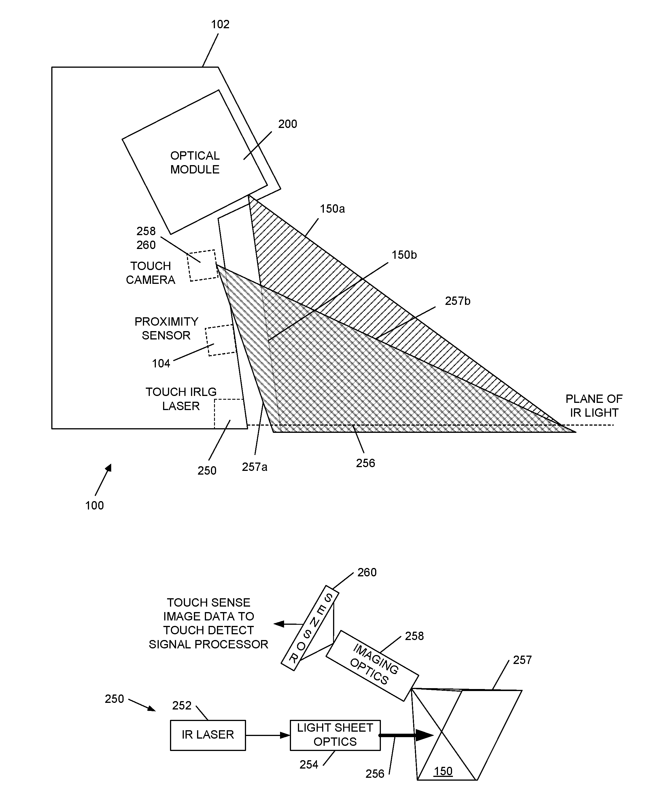
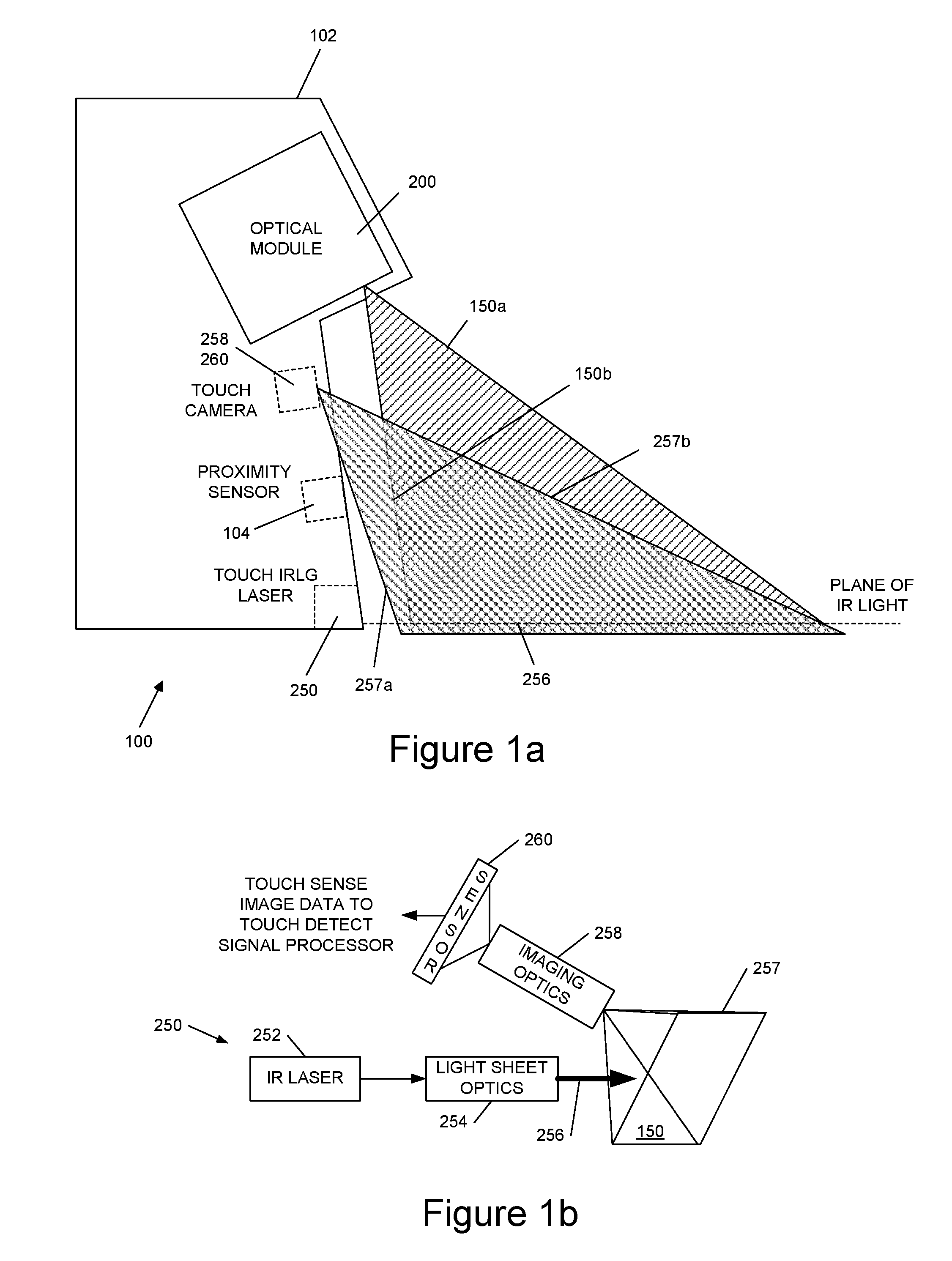
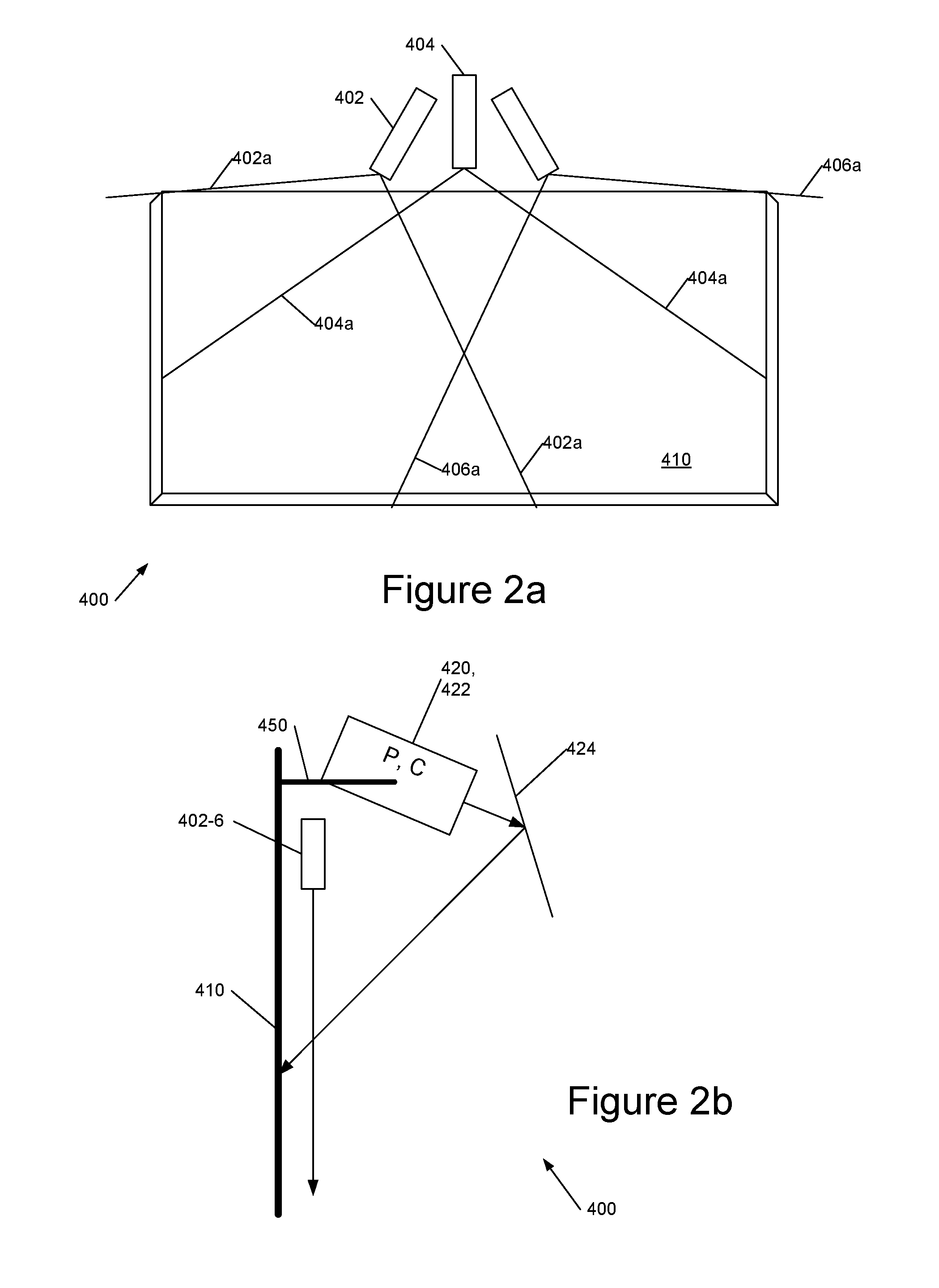
[0044]Broadly speaking we will describe touch detection systems based upon a scanning laser beam for detecting touches on, or proximate to, a surface. Thus referring to FIG. 3, this shows a touch sensing system 300 comprising a polygonal rotating scanning mirror 302 illuminated by a laser 304 followed by optional collimation optics 306 providing a collimated beam 308 of, for example, infrared light. Rotation of the polygonal scanner (mirror) 302 generates a scanned beam 310, the locus or envelope of the scanned beam defining a surface 312, typically a plane, for touch sensing. As illustrated, in a typical application this is located just above a display surface 314 such as a wall or white board onto which an image may be projected, a flat panel display, and the like. As the beam 310 scans through the touch surface 312, over the display surface 314, light 320 from one or more objects 318 on the surface, for example one or more fingers, is scattered back towards scanner 302. This ligh...


PUM


Abstract

Various approaches to touch sensing systems are disclosed As an example, a touch sensing system is disclosed that includes: an optical beam source to provide an optical beam; a pair of controllable beam deflectors comprising at least first and second beam deflectors, wherein the first beam deflector is configured to deflect the optical beam through a first angle towards a touch sensing region, and wherein the second beam deflector is configured to deflect scattered light from an object in the touch sensing region through a second angle; a detector, in particular a detector array; and an imaging system to image the deflected scattered light from the second beam deflector onto the detector array. The first and second beam deflectors are controlled in tandem to scan the touch sensing region.

Description

CROSS REFERENCE TO RELATED APPLICATION[0001]This application claims priority to GB Application No. GB1214465.5 entitled “Scanning Touch Sensing Systems” and filed Aug. 14, 2012 and PCT Application PCT / GB2013 / 052150 filed Aug. 13, 2013. The entirety of the aforementioned applications are incorporated herein by reference for all purposes.FIELD OF THE INVENTION[0002]This invention relates touch sensing systems and methods which, in embodiments, can be used to provide a virtual touch sensing surface just above a display screen, white board or the like.BACKGROUND OF THE INVENTION[0003]We have previously described touch sensing systems employing a plane or sheet of light, for example as shown in FIGS. 1 and 2. These techniques may be employed for detecting touches or proximate to a surface.[0004]FIG. 1 shows an example touch sensitive image projection device 100 comprising an image projection module 200 and a touch sensing system 250, 258, 260 in a housing 102. A proximity sensor 104 may ...

Claims


Application Information

Patent Timeline
Patent Type & Authority Applications(United States)
IPC IPC(8): G06F3/042
CPCG06F3/0423G06F3/0421G06F3/0426G06F3/0428
Inventor CABLE, ADRIAN JAMESRICHARD, PAULSMITH, EUAN CHRISTOPHERMCCAHGHAN, GARETH JOHNMASH, PETER WILLIAM TUDOR
Owner LIGHT BLUE OPTICS
Why Eureka
Try Eureka