Drilling apparatus

a technology of drilling apparatus and rod section, which is applied in the direction of drilling accessories, earthwork drilling and mining, storage devices, etc., can solve the problems of high wear of rod sections and transfer devices, and achieve the effects of high stability, reliable operation, and great gripping for

Active Publication Date: 2011-08-18
TRACTO TECHN
View PDF23 Cites 6 Cited by
  • Summary
  • Abstract
  • Description
  • Claims
  • Application Information

AI Technical Summary

Benefits of technology

[0016]According to another advantageous feature of the present invention, each of the grippers may include at least two gripping elements which are swingable about a pivot axis and capable of being acted upon by a wedge in the direction of their closed position. Displacing the wedge in order to act upon the gripping elements may hereby be realized preferably by means of a fluid cylinder. By having a wedge act upon the gripping elements, sufficiently great gripping forces can be exerted upon the rod section in a structurally simple manner.
[0017]According to another advantageous feature of the present invention, the transfer device may include a spring to bias the gripping elements as to seek their open position. In this way, the grippers can be completely released from the rod section, when the wedges of the grippers retract.
[0018]According to another advantageous feature of the present invention, the transfer device may include further drives to move the gripping unit in a direction of two further axes in relation to the rod magazine in addition to the movement in the longitudinal direction of the rod section. Suitably, the axes may extend perpendicular to one another. In this way, it is possible, to arrange the rod magazine fixed in relation to the drill rig and for example to the side and above the drill rig, and to realize the required height and lateral movements of the rod section in order to be brought from a transfer position of the rod magazine into the coaxial position with the drilling rod axis solely by a movement of the transfer device. In particular the need for a movement of the rod magazine, loaded with a plurality of rod sections and thus possibly heavy rod magazine, can thereby be eliminated.
[0019]A movement of the transfer device along the two further axes may be realized advantageously by means of two rack-and-pinion drives because in this way even greater travel paths can be realized in a constructively simple manner. In addition, rack-and-pinion drives are characterized by a high stability and reliable operation. Of course, any other drives may be used, especially linear drives, for moving the transfer device. For example, hydraulically or pneumatically driven cylinders or also spindles driven by a motor (e.g. electric motor, hydraulic motor, etc.) can be used.
[0020]Each of the rack-and-pinion drives may advantageously include a fluid motor so that again the fluid supply typically present in drilling apparatuses can be used.

Problems solved by technology

This prior art has the drawback that a movement of the rod section to be newly attached towards the rear end of the drilling rod requires a shift of the rod section in the mounting of the rod transfer device, causing high wear of the rod section as well as of the transfer device, in particular when clamping the rod section in the rod transfer device is involved.

Method used


Image

  • Drilling apparatus
  • Drilling apparatus
  • Drilling apparatus

Examples


Embodiment Construction

[0026]Throughout all the figures, same or corresponding elements may generally be indicated by same reference numerals. These depicted embodiments are to be understood as illustrative of the invention and not as limiting in any way. It should also be understood that the figures are not necessarily to scale and that the embodiments are sometimes illustrated by graphic symbols, phantom lines, diagrammatic representations and fragmentary views. In certain instances, details which are not necessary for an understanding of the present invention or which render other details difficult to perceive may have been omitted.

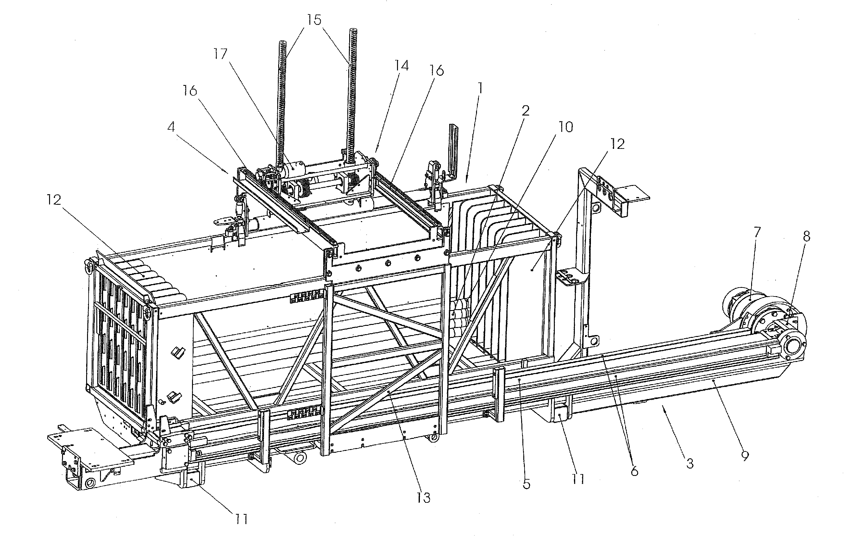
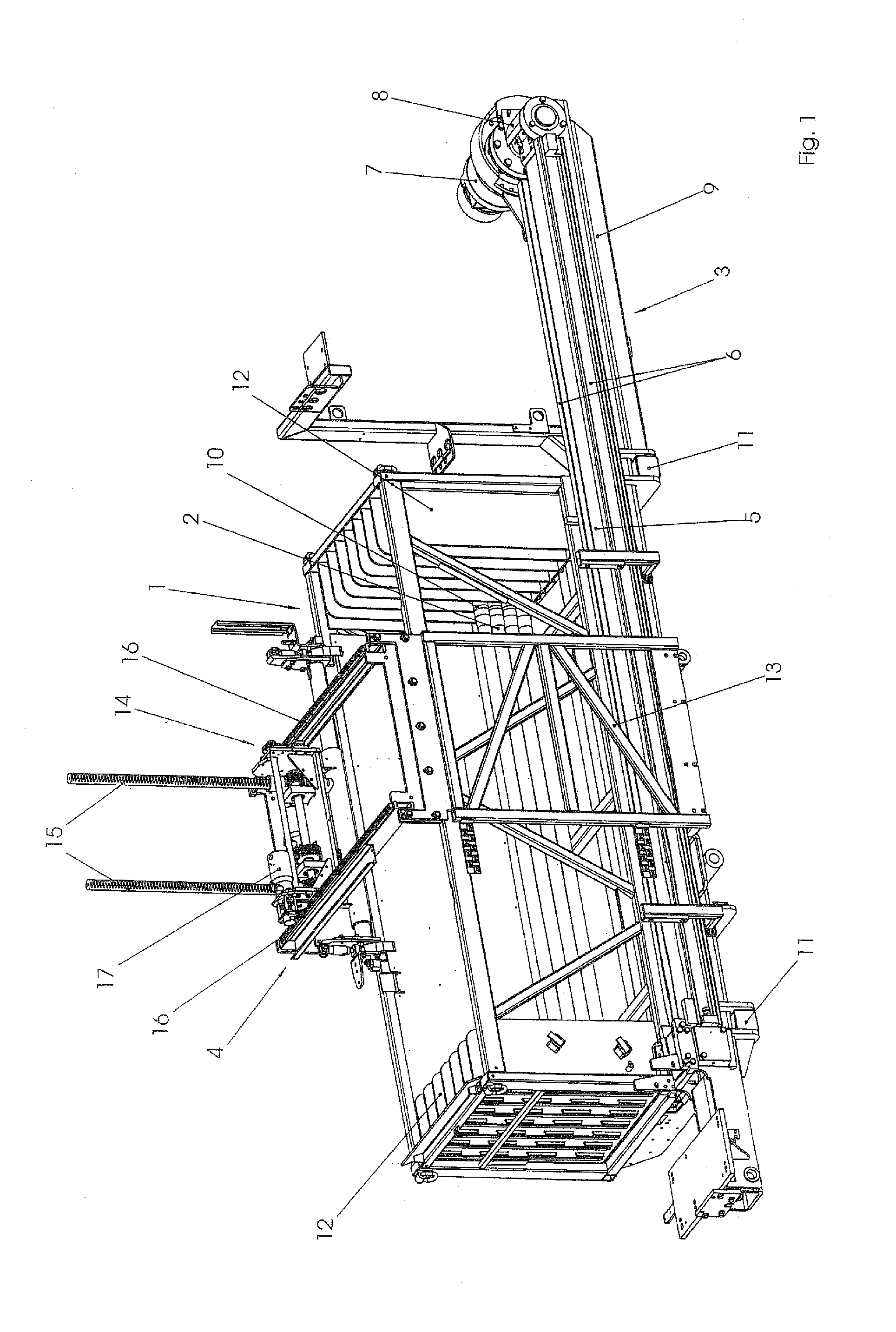
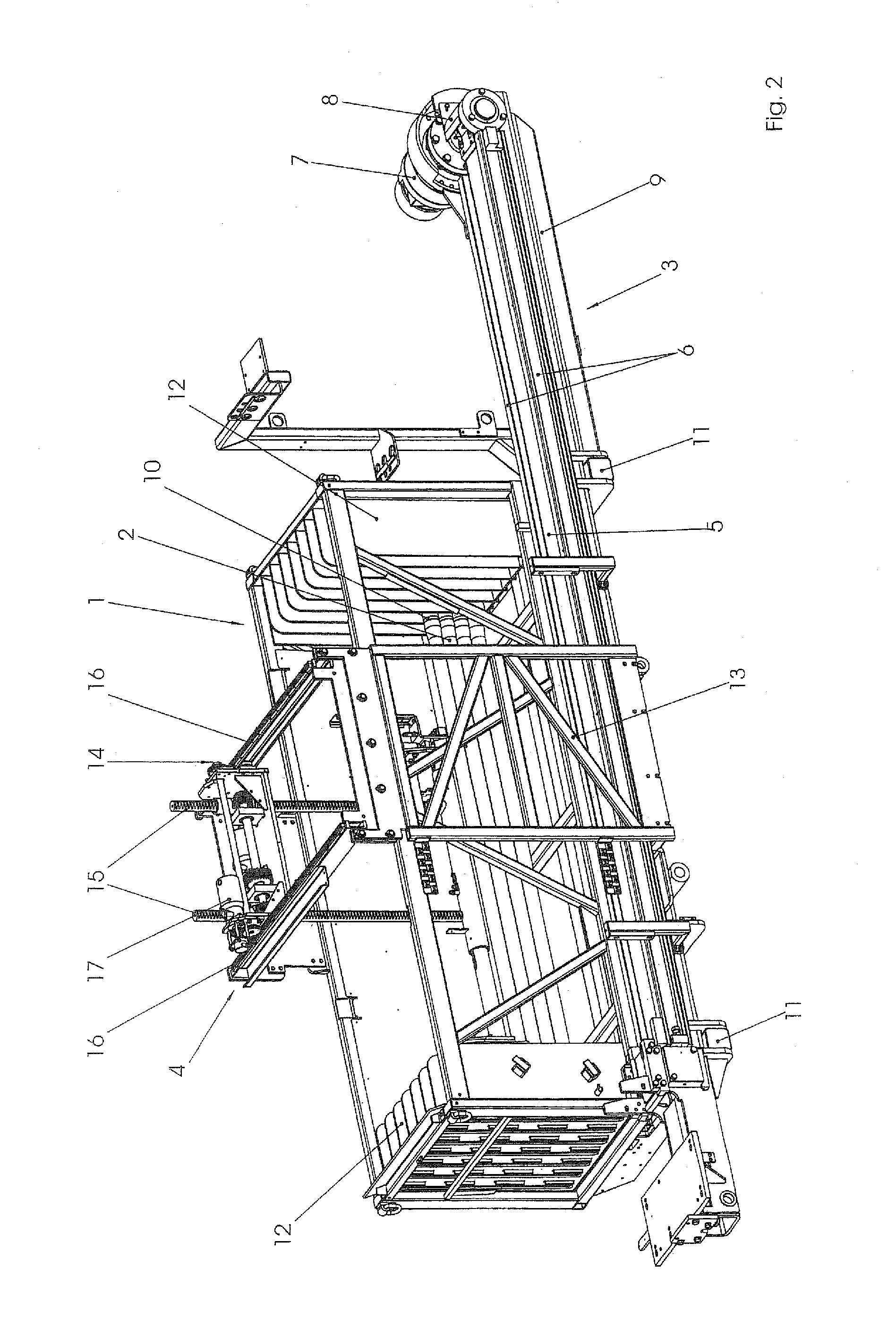
[0027]Turning now to the drawing, and in particular to FIG. 1, there is shown an isometric illustration of a drilling apparatus according to the present invention in a first operative position. The drilling apparatus includes as essential assemblies a rod magazine 1 with a plurality of stored rod sections 2, a drill rig 3 of which only a part is shown, as well as a transfer ...


PUM


Abstract

A drilling apparatus includes a drill rig which defines a drilling rod axis, a rod magazine for a plurality of rod sections, and a transfer device for transfer of a rod section from the rod magazine and for transfer of the rod section in the drilling rod axis. The transfer device is hereby constructed to travel in the direction of the longitudinal axis of the rod section in relation to the rod magazine.

Description

CROSS-REFERENCES TO RELATED APPLICATIONS[0001]This application claims the priority of German Patent Application, Serial No. 10 2009 035 277.5, filed Jul. 29, 2009, pursuant to 35 U.S.C. 119(a)-(d), the content of which is incorporated herein by reference in its entirety as if fully set forth herein.BACKGROUND OF THE INVENTION[0002]The present invention relates in general to a drilling apparatus for underground works.[0003]The following discussion of related art is provided to assist the reader in understanding the advantages of the invention, and is not to be construed as an admission that this related art is prior art to this invention.[0004]When introducing boreholes in the ground and in particular when horizontal drilling is involved in which a borehole, starting from the surface or a starting shaft provided in the ground, is made horizontally or slantingly into the soil, drilling rod assemblies are typically used comprised of individual rod sections which are successively connec...

Claims


Application Information

Patent Timeline
Patent Type & Authority Applications(United States)
IPC IPC(8): E21B19/15
CPCE21B19/20E21B19/15E21B19/086
Inventor HERMES, STEFANGROBBEL, RAIMUND
Owner TRACTO TECHN
Why Eureka
Try Eureka