

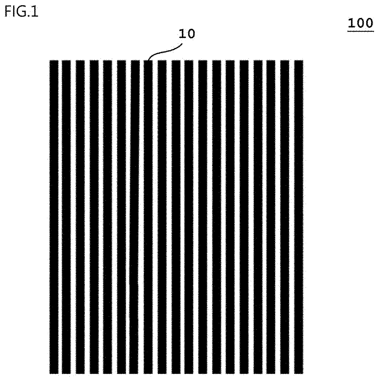
Carbon nanotube aggregate
a carbon nanotube and aggregate technology, applied in the field of carbon nanotube aggregate, can solve the problems of difficult material to maintain the same level of gripping force in a wide temperature range, unable to sufficiently hold the object for processing, and elastic material is liable to adhere to and remain on the object, etc., and achieve excellent gripping force
- Summary
- Abstract
- Description
- Claims
- Application Information
AI Technical Summary
Benefits of technology
Problems solved by technology
Method used
Image

Examples
example 1
[0091]An Al2O3 thin film (ultimate vacuum: 8.0×10⁻⁴ Pa, sputtering gas: Ar, gas pressure: 0.50 Pa) was formed in an amount of 3,922 ng / cm2 on a silicon base material (manufactured by Valqua FFT Inc., thickness: 700 μm) with a sputtering apparatus (manufactured by Shibaura Mechatronics Corporation, product name: “CFS-4ES”). An Fe thin film was further formed as a catalyst layer (sputtering gas: Ar, gas pressure: 0.75 Pa) in an amount of 294 ng / cm2 on the Al2O3 thin film with a sputtering apparatus (manufactured by Shibaura Mechatronics Corporation, product name: “CFS-4ES”).
[0092]After that, the base material was placed in a quartz tube of 30 mmcp, and a helium / hydrogen (105 / 80 sccm) mixed gas having its moisture content kept at 700 ppm was flowed into the quartz tube for 30 minutes to replace the inside of the tube. After that, the temperature in the tube was increased with an electric tubular furnace to 765° C. and stabilized at 765° C. While the temperature was kept at 765° C., the...
example 2
[0098]A carbon nanotube aggregate was produced in the same manner as in Example 1.
[0099]The carbon nanotube aggregate of a sheet shape was peeled from the silicon base material, and the surface that had been on the opposite side to the silicon base material at the time of the production of the carbon nanotube aggregate was arranged as it was on the silicon base material. Thus, an evaluation sample (2A) was produced. An exposed carbon nanotube aggregate surface in the evaluation sample (2A) (i.e., the surface that had been on the silicon base material side at the time of the production of the carbon nanotube aggregate) was subjected to the evaluation described in the section (1). The result is shown in Table 1.
[0100]The carbon nanotube aggregate of a sheet shape was peeled from the silicon base material, and the surface that had been on the opposite side to the silicon base material at the time of the production of the carbon nanotube aggregate was fixed to a glass slide base materia...
example 3
[0102]An Al2O3 thin film (ultimate vacuum: 8.0×10⁻⁴ Pa, sputtering gas: Ar, gas pressure: 0.50 Pa) was formed in an amount of 3,922 ng / cm2 on a silicon base material (manufactured by Valqua FFT Inc., thickness: 700 μm) with a sputtering apparatus (manufactured by Shibaura Mechatronics Corporation, product name: “CFS-4ES”). An Fe thin film was further formed as a catalyst layer (sputtering gas: Ar, gas pressure: 0.75 Pa) in an amount of 294 ng / cm2 on the Al2O3 thin film with a sputtering apparatus (manufactured by Shibaura Mechatronics Corporation, product name: “CFS-4ES”).
[0103]After that, the base material was placed in a quartz tube of 30 mmφ, and a helium / hydrogen (85 / 60 sccm) mixed gas having its moisture content kept at 600 ppm was flowed into the quartz tube for 30 minutes to replace the inside of the tube. After that, the temperature in the tube was increased with an electric tubular furnace to 765° C. and stabilized at 765° C. While the temperature was kept at 765° C., the i...
PUM
| Property | Measurement | Unit |
|---|---|---|
| angle | aaaaa | aaaaa |
| angle | aaaaa | aaaaa |
| angle | aaaaa | aaaaa |
Abstract
Description
Claims
Application Information