Low profile connector system

a connector system and low-profile technology, applied in the direction of coupling device connection, electrical discharge lamp, coupling device details, etc., can solve the problems of limiting the thickness of the corresponding receptacle, the 3.5 mm size of the plug diameter of the standard audio plug connector, and the inability of the connector system to backward compatibility with the multitude of existing devices and accessories designed with the 3.5 mm size in mind

Inactive Publication Date: 2011-08-18
APPLE INC
View PDF28 Cites 219 Cited by
  • Summary
  • Abstract
  • Description
  • Claims
  • Application Information

AI Technical Summary

Benefits of technology

[0007]In another set of embodiments, the low profile connector system can include different types of custom plug connectors that are adapted to mate with the low profile plug receptacle described above. For example, one type of custom plug connector can include a cosmetic cap that is coupled with the connector plug and / or the connector body. When the custom plug connector is inserted into the low profile plug receptacle, the cosmetic cap can at least partially cover the second opening of the receptacle (including the portion of the plug extending through the second opening). In certain embodiments, the outer surface of the cosmetic cap can be configured to be similar in appearance to an outer surface of an electronic device housing the low profile plug receptacle. In this manner, the cosmetic cap can improve the aesthetics of the device when the custom plug connector is attached.
[0008]Another type of custom plug connector can include a plug that is shaped to match the longitudinal passage inside the low profile plug receptacle. For instance, if the second opening causes the longitudinal passage to be partially cylindrical (rather than fully cylindrical) in shape, the plug of the custom plug connector can also be partially cylindrical in shape. Thus, the custom plug connector can be inserted into the low profile plug receptacle in such a way that no portion of the plug extends through the second opening. This also can improve the aesthetics the electronic device housing the receptacle.
[0009]In another set of embodiments, the low profile connector system can include features for preventing a plug connector from unintentionally falling out of, or coming loose from, the low profile plug receptacle and / or preventing a plug connector from rotating within the receptacle. For example, in embodiments where the plug connector can be customized, the low profile plug receptacle can include a magnet and the custom plug connector can include a ferrous attractor (or vice versa). When the custom plug connector is inserted into the low profile plug receptacle, the magnetic attraction between the magnet and ferrous attractor can cause the plug connector to be held in place.
[0011]In embodiments where the plug connector can be a standard connector (e.g., a 3.5 mm miniature connector), the low profile connector system can include an adapter that is separate from either the low profile plug receptacle or the standard plug connector, and can be configured to attach onto or around one or more outer walls of an electronic device in which the low profile plug receptacle is housed. When the adapter is attached, the adapter can provide structural support that prevents the standard plug connector from unintentionally coming loose from the low profile plug receptacle, thereby providing improved compatibility with such standard connectors.

Problems solved by technology

As electronic devices (such as portable media players, cellular phones, portable computing devices, and the like) become smaller and thinner, the plug diameter of standard audio plug connectors (and the thickness of their corresponding receptacles) can be a limiting factor in reducing device thickness.
While it is possible to develop an audio plug connector and receptacle that uses a smaller plug diameter than, for example, the standard 3.5 mm miniature size, such a connector system would not be backward compatible with the multitude of existing devices and accessories that are designed with the 3.5 mm size in mind.

Method used


Image

  • Low profile connector system
  • Low profile connector system
  • Low profile connector system

Examples


Embodiment Construction

[0024]In the following description, for the purposes of explanation, numerous details are set forth in order to provide an understanding of various embodiments of the present invention. It will be apparent, however, to one skilled in the art that certain embodiments can be practiced without some of these details.

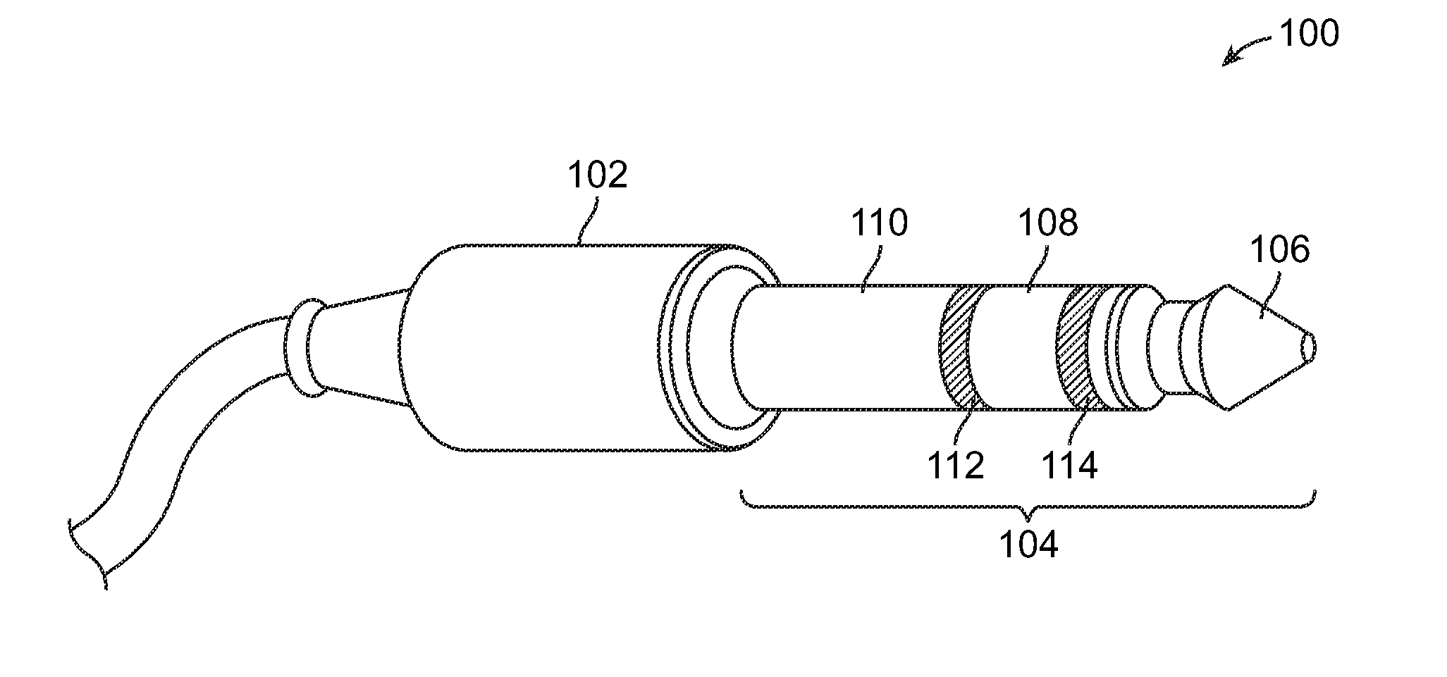
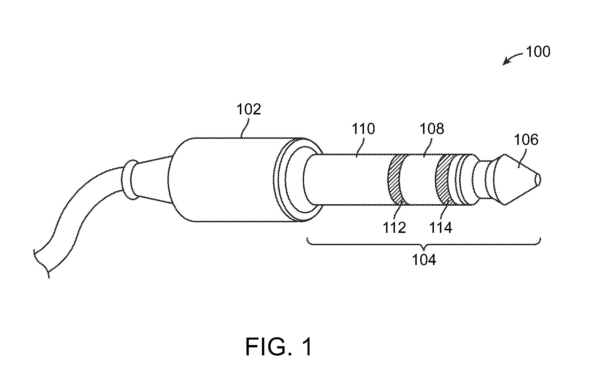
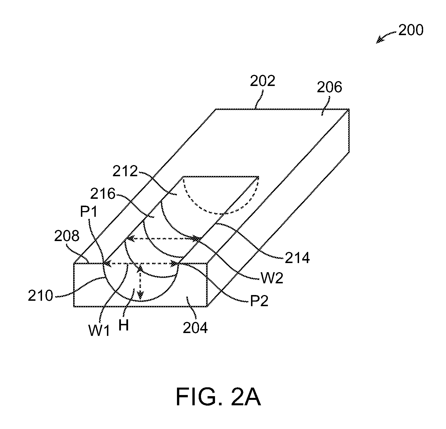
[0025]Embodiments of the present invention provide a low profile connector system. In one set of embodiments, a low profile plug receptacle is provided that is thinner than a standard plug receptacle, thereby allowing the low profile plug receptacle to be incorporated in small form factor (e.g., very thin) electronic devices while maintaining compatibility with standard (e.g., 3.5 mm) plug connectors. In another set of embodiments, different types of custom plug connectors are provided that can improve the aesthetics of an electronic device housing the low profile plug receptacle when the custom plug connector attached. In another set of embodiments, features are provided fo...


PUM


Abstract

A low profile connector system. In one set of embodiments, a low profile plug receptacle is provided that is thinner than a standard plug receptacle, thereby allowing the plug receptacle to be incorporated in small form factor (e.g., very thin) electronic devices while maintaining compatibility with standard plug connectors. In another set of embodiments, different types of custom plug connectors are provided that can improve the aesthetics of an electronic device housing the low profile plug receptacle when the custom plug connector is attached. In another set of embodiments, features are provided for preventing a plug connector from unintentionally falling out of, or coming loose from, the low profile plug receptacle and / or preventing a plug connector from rotating within the receptacle.

Description

CROSS-REFERENCES TO RELATED APPLICATIONS[0001]The present application is related to co-pending U.S. patent application Ser. No. 12 / 205,333 (Attorney Docket No. 20750P-008100US) titled “Low Profile Plug Receptacle,” filed Sep. 5, 2008, which is incorporated herein by reference in its entirety for all purposes.BACKGROUND[0002]Embodiments of the present invention relate generally to connector systems, and in particular to a low profile connector system that can be used with small form factor electronic devices.[0003]Standard audio plug connectors (or “audio plugs”) include a cylindrical plug and are available in three sizes according to the diameter of the plug: a 6.35 mm (¼″) size, a 3.5 mm (⅛″) “miniature” size, and a 2.5 mm ( 3 / 32″) “subminiature” size. Generally speaking, these connectors have conductive regions along portions of the plug known as the tip, ring, and sleeve, and are thus often referred to as TRS (tip, ring, sleeve) connectors.[0004]FIG. 1 is a perspective view of a ...

Claims


Application Information

Patent Timeline
Patent Type & Authority Applications(United States)
IPC IPC(8): H01R11/30H01R24/00H01R24/04
CPCH01R2105/00H01R24/58
Inventor DABOV, TEOFRAZIER, CAMERON
Owner APPLE INC
Why Eureka
Try Eureka