Lock structure for battery charging connector

a technology of charging connector and lock structure, which is applied in the direction of charging device connection, propulsion by batteries/cells, transportation and packaging, etc., can solve the problems of user theft of power feeding connector itself, time required to charge the battery of an electric vehicle is still much longer than the time required to refuel, and user would most likely leave the vehicle unattended

Active Publication Date: 2011-08-18
KK TOKAI RIKA DENKI SEISAKUSHO
View PDF2 Cites 55 Cited by
  • Summary
  • Abstract
  • Description
  • Claims
  • Application Information

AI Technical Summary

Problems solved by technology

Although fast charging technology is being developed, the time required to charge the battery of an electric vehicle is still much longer than that required to refuel a gasoline engine vehicle.
Hence, the user would most likely leave the vehicle unattended to when the battery is being char

Method used


Image

  • Lock structure for battery charging connector
  • Lock structure for battery charging connector
  • Lock structure for battery charging connector

Examples


Embodiment Construction

[0027]A power feeding connector for a plug-in hybrid vehicle according to one embodiment of the present invention will now be discussed.

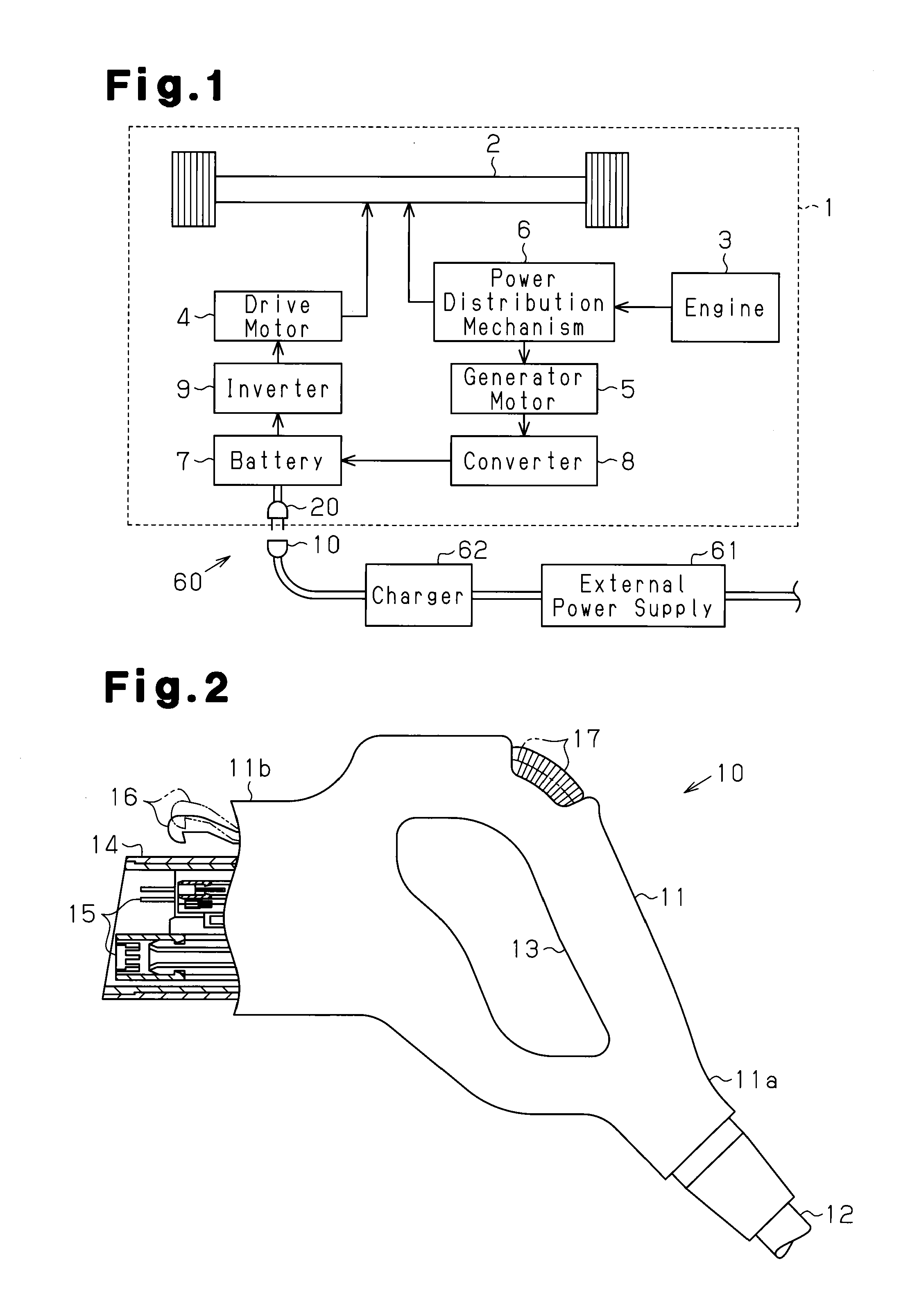
[0028]Referring to FIG. 1, a plug-in hybrid vehicle 1 includes an engine 3 and a drive motor 4, each used as drive source for drive wheels 2. The vehicle 1 is switched between a plurality of drive modes when driven. The drive modes include a mode that uses only the engine 3 to drive the drive wheels 2, a mode using the drive motor 4 while generating electric power with the engine 3 to drive the drive wheels 2, a mode using both the engine 3 and the drive motor 4 to drive the drive wheels 2, and a mode using only the drive motor 4 to drive the drive wheels 2.

[0029]A power distribution mechanism 6 is arranged between the engine 3 and the drive wheels 2 to distribute the power generated by the engine 3 to the drive wheel 2 and a generator motor 5. The generator motor 5 uses the power of the engine 3 to produce rotation and generate power. The generator...


PUM


Abstract

A battery charging connector lock structure that locks a power feeding connector to a receptacle of a power receiving connector. The connector lock structure includes a restriction member that moves between a lock position, in which the restriction member restricts movement of a hook of the power feeding connector to prohibit removal of the power feeding connector from the receptacle, and an unlock position, in which the restriction member releases the hook to permit removal of the power receiving connector. The restriction member includes an extension. A stopper is coupled to the extension of the restriction member and moves the restriction member to the lock position or the unlock position. A drive source moves the stopper to move the restriction member to the lock position. An urging member is arranged on the extension of the restriction member to move the restriction member to the lock position.

Description

CROSS-REFERENCE TO RELATED APPLICATIONS[0001]This application is based upon and claims the benefit of priority from prior Japanese Patent Application No. 2010-28957, filed on Feb. 12, 2010, the entire contents of which are incorporated herein by reference.BACKGROUND OF THE INVENTION[0002]The present invention relates to a lock structure arranged in a power receiving connector to lock the power receiving connector with a power feeding connector when charging a battery.[0003]Automobile manufacturers are developing electric vehicles to reduce exhaust emissions from vehicles. An electric vehicle uses a battery as a power source. Whenever the state of charge of the battery becomes low, the user of the electric vehicle must charge the battery with a charger that is installed in a household or a charging station. Charging systems that are easy for a user to use have been disclosed (for example, Japanese Laid-Open Patent Publication No. 9-161898). The prior art charging system includes a po...

Claims


Application Information

Patent Timeline
IPC IPC(8): H01R13/62
CPCB60L11/123B60L11/14B60L11/1818H01R13/6275H01R13/6397B60L2270/34Y02T10/6217Y02T10/7005Y02T10/7077Y02T90/14B60L2270/32H01R2201/26B60L50/16B60L50/61B60L53/16Y02T10/62Y02T10/70Y02T10/7072
Inventor KURUMIZAWA, NAOTOYAMAMOTO, MAKOTO
Owner KK TOKAI RIKA DENKI SEISAKUSHO
Why Eureka
Try Eureka