Facing element and method of fabricating thereof

Inactive Publication Date: 2011-08-25
MATYS TYLER +1
View PDF9 Cites 12 Cited by
  • Summary
  • Abstract
  • Description
  • Claims
  • Application Information

AI Technical Summary

Benefits of technology

[0028]The present invention introduces an integrated connector system into the back of the panel during the wet casting process, thereby negating the need fo

Problems solved by technology

This approach has numerous drawbacks and l

Method used


Image

  • Facing element and method of fabricating thereof
  • Facing element and method of fabricating thereof
  • Facing element and method of fabricating thereof

Examples


Embodiment Construction

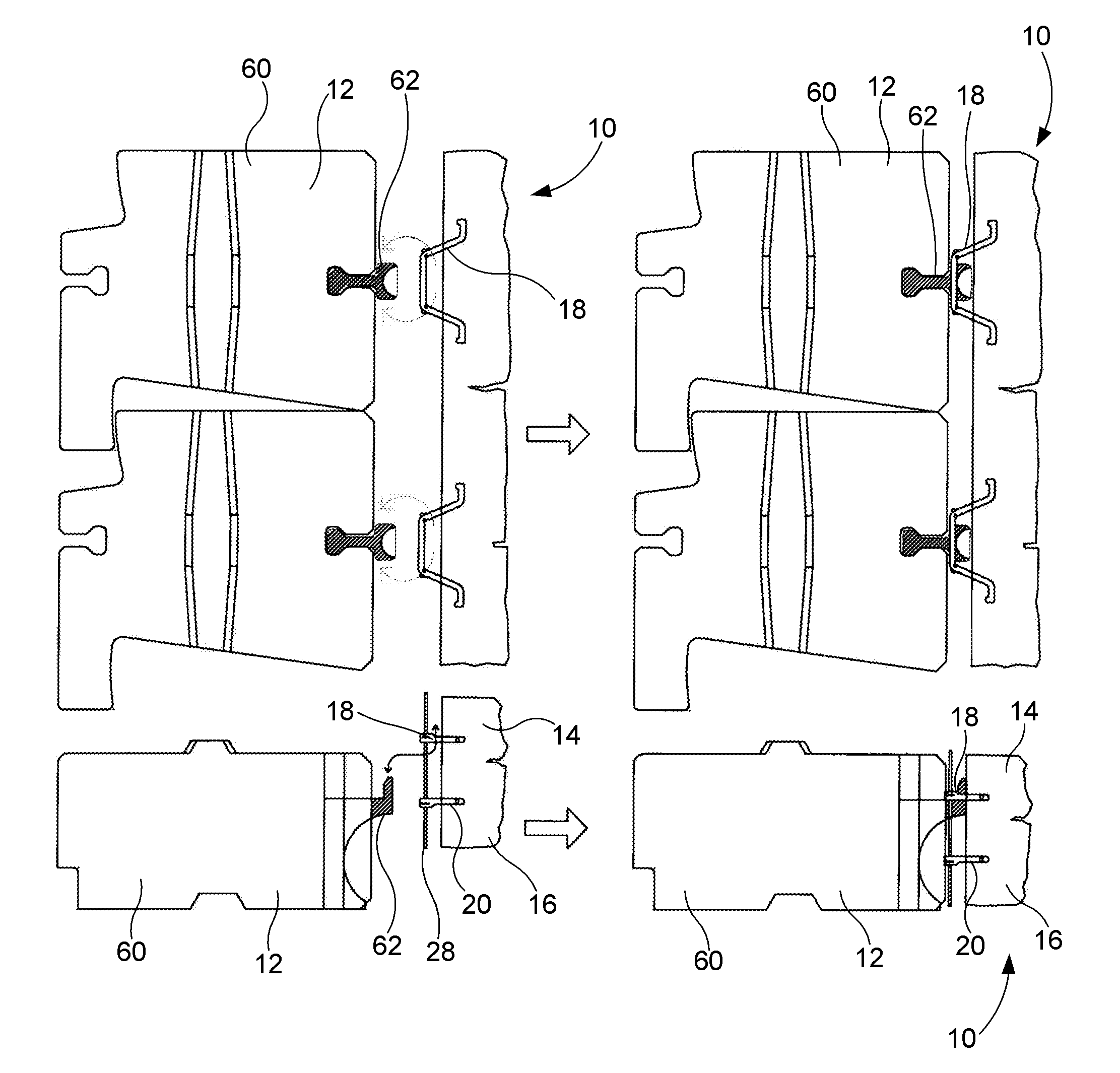
[0056]FIGS. 1 to 4 and 13 to 18 illustrate a facing element 10 and components thereof according to a first preferred embodiment of the present invention.

[0057]The facing element 10 is to be used for at least partially covering a structure 12, as shown in FIGS. 15 to 18. As better shown in FIG. 13, the facing element 10 comprises a top portion 14 and a bottom portion 16. The facing element also comprises at least one pair of first and second rigid engagement connectors 18,20 affixed to a rear surface 22 of the facing element 10. Each of the first and second engagement connectors 18,20 forms first and second apertures 24,26 between the connectors 18,20 and the rear surface 22 of the facing element 10. The first and second apertures 24,26 are coaxially located.

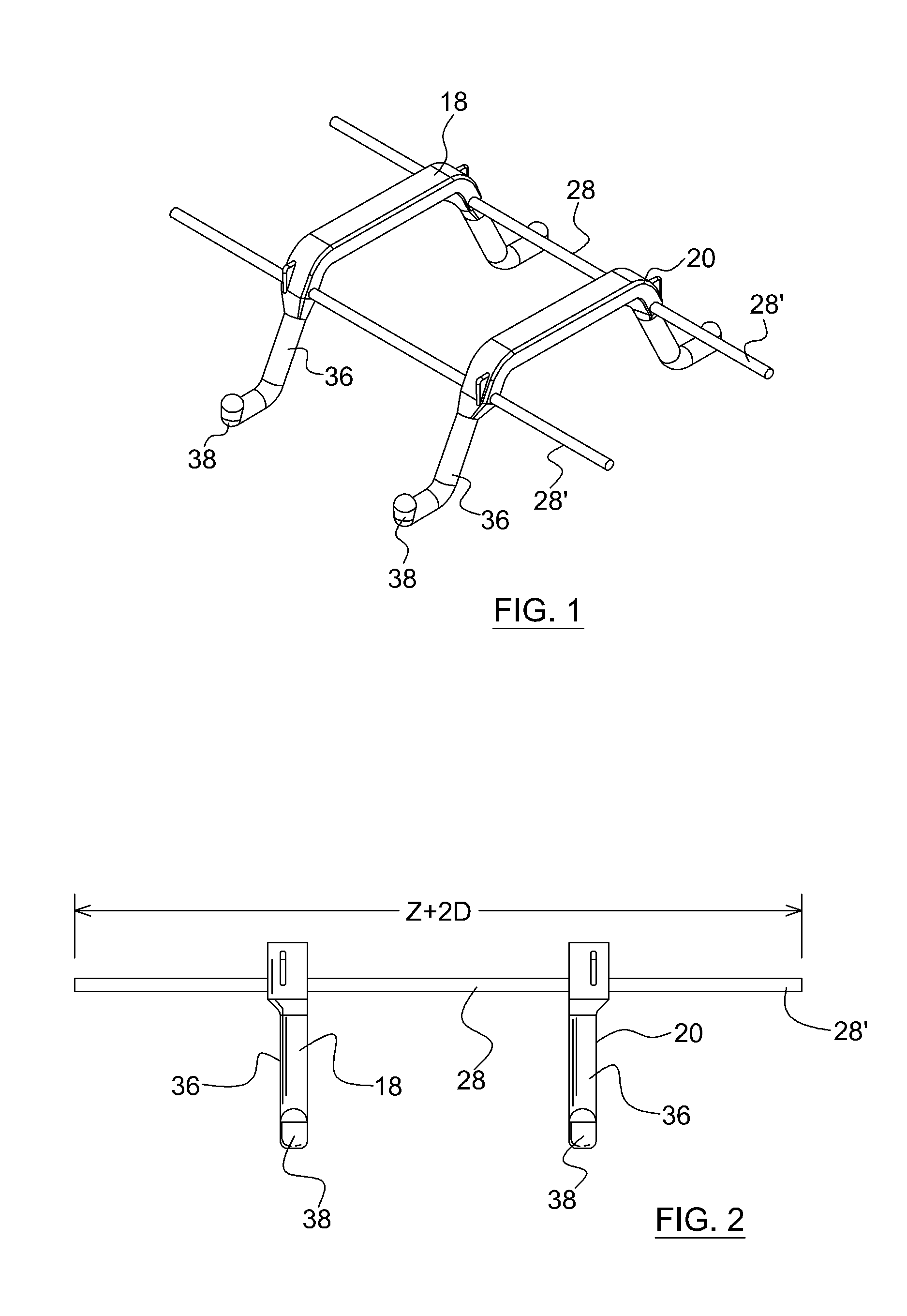
[0058]As better shown in FIGS. 1 to 3, the facing element 10 also comprises at least one joining bar 28 joining the first and second engagement connectors 18,20. As better shown in FIGS. 15 and 16, the top portion 14 of the facin...


PUM

PropertyMeasurementUnit
Angleaaaaaaaaaa
Structureaaaaaaaaaa

Abstract

A facing element for at least partially covering a structure. The facing element has at least one pair of first and second rigid engagement connectors affixed to a rear surface of the facing element. Each of the first and second engagement connectors forms first and second apertures between the connectors and the rear surface of the facing element. The first and second apertures are coaxially located. The facing element also has at least one joining bar joining the first and second engagement connectors. The top portion of the facing element is hung to the structure by means of the first engagement connector. Contact of the bottom portion of the facing element with the structure is offset by the second engagement connector. A method for fabricating such a facing element is also disclosed.

Description

RELATED APPLICATIONS[0001]This application is the U.S. National Phase under 35 U.S.C. §371 of International Application No. PCT / CA2009 / 001435, filed on Oct. 8, 2009, which in turn claims the benefit of U.S. Provisional Application No. 61 / 103,667, filed on Oct. 8, 2008, the disclosures of which Applications are incorporated by reference herein.FIELD OF THE INVENTION[0002]The present invention generally relates to facing elements. More specifically, the present invention relates to a facing element for at least partially covering a structure, and a method of fabricating such an element.BACKGROUND OF THE INVENTION[0003]The present invention relates to the combination of a wet cast concrete mold system, integrated connector or mounting system, and related process for wet casting relatively small and light concrete veneers used as a facing element or façade for small buildings, retaining walls, or other structures.[0004]The purpose of the wet cast concrete veneer is to provide a more aes...

Claims


Application Information

Patent Timeline
IPC IPC(8): E04C2/04B29C39/10
CPCB28B23/005B28B23/0056E04B1/41E04F13/083E04F13/0832E04F13/141E04F13/147E04F13/0816
Inventor MATYS, TYLERRISI, ANGELO
Owner MATYS TYLER
Why Eureka
Try Eureka