Solar cell module stand and solar power generation system using same

a solar cell and solar panel technology, applied in the direction of machine supports, heat collector mounting/supports, light and heating apparatus, etc., can solve the problems of complex operation of providing earth wires in solar cell panels, and achieve the effect of simple operation, stable grounding of solar cell modules, and elimination of complex tasks

Inactive Publication Date: 2011-08-25
SHARP KK
View PDF9 Cites 10 Cited by
  • Summary
  • Abstract
  • Description
  • Claims
  • Application Information

AI Technical Summary

Benefits of technology

[0021]With the solar cell module stand of the present invention, stable grounding for solar cell modules can be accomplished with a simple operation. Also, with a solar power generation system using such a solar cell module stand, it is possible, for each solar cell module, to make a wire connection for grounding solar cell modules simultaneously with installation of the solar cell module, and therefore complex tasks can be eliminated.

Problems solved by technology

However, it is a complex operation to provide an earth wire in the solar cell panels because an insulating film is provided on the outer surface of the frames of the solar cell modules formed of a conductive metal body.

Method used


Image

  • Solar cell module stand and solar power generation system using same
  • Solar cell module stand and solar power generation system using same
  • Solar cell module stand and solar power generation system using same

Examples


Embodiment Construction

[0047]Hereinafter, embodiments of the present invention will be described in detail with reference to the drawings.

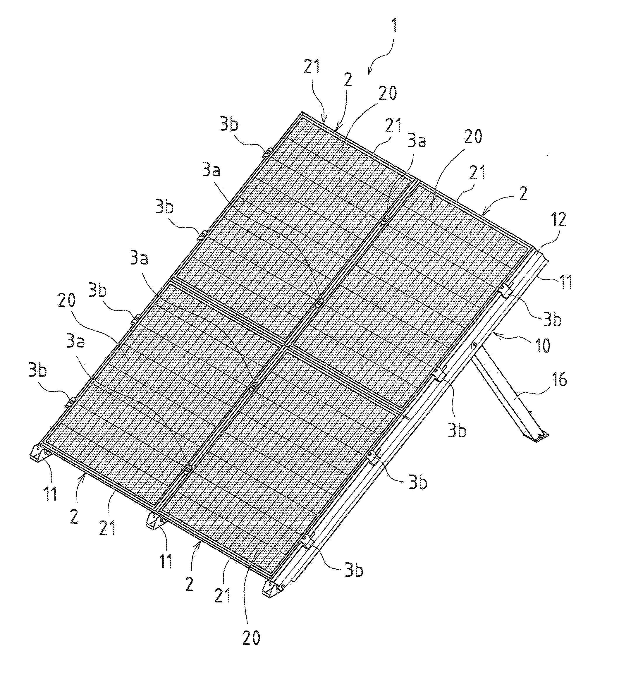
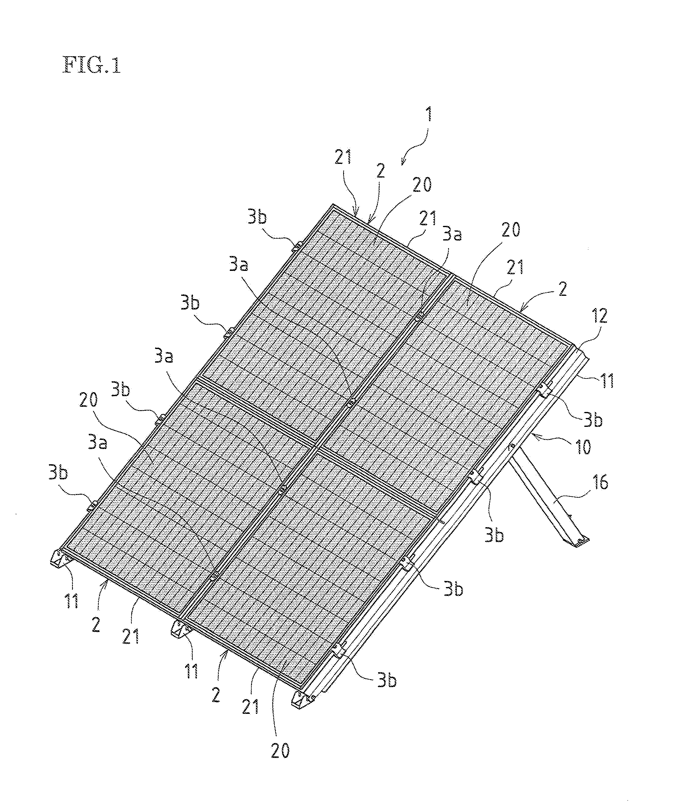
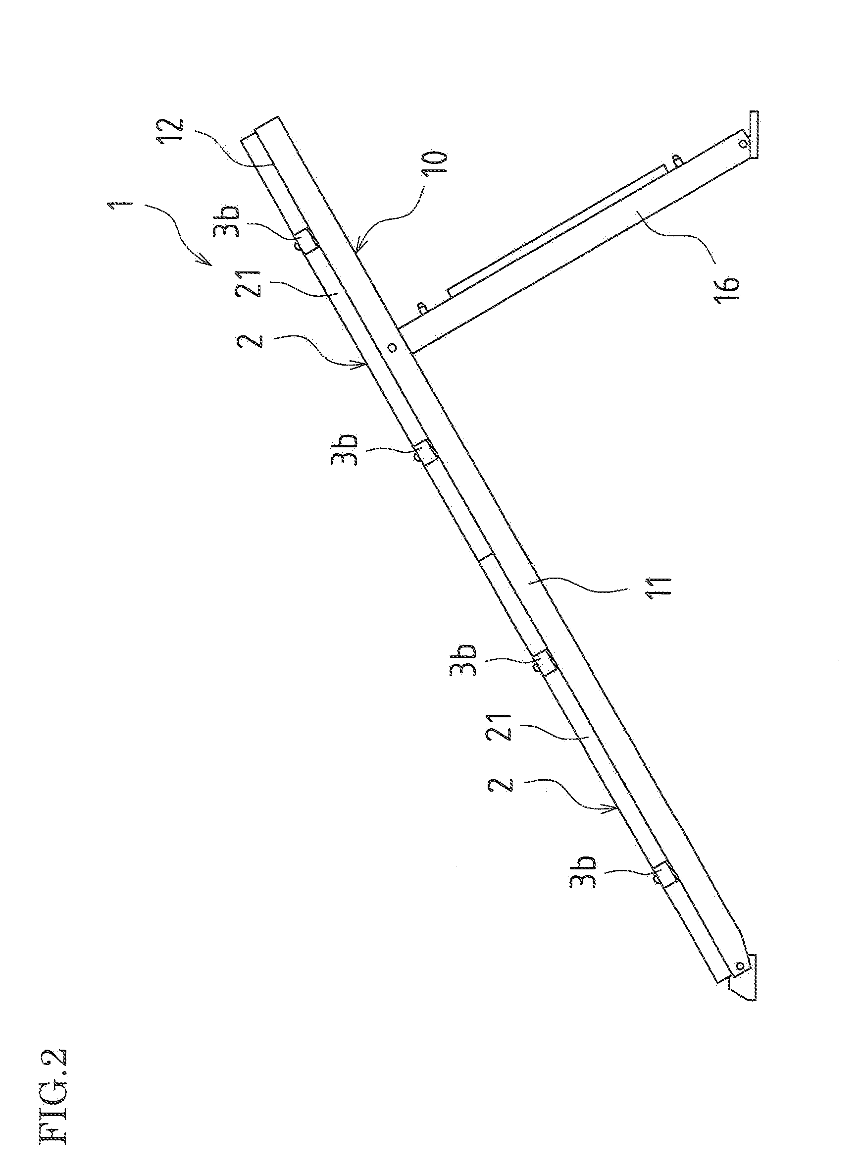
[0048]FIG. 1 is a perspective view of a solar cell module stand according to a first embodiment of the present invention. FIG. 2 is a side view of a stand unit according to the first embodiment.

[0049]In a solar cell module stand 1 of the present embodiment, three stand units 10 as shown in FIG. 2 are used. The stand units 10 are provided side by side on the roof, on the ground or the like, and as shown in FIG. 1, four solar cell modules 2 are mounted and fixed onto the stand units 10.

[0050]Each solar cell module 2 is constituted by a solar cell panel 20 and a frame member 21 for holding the solar cell panel 20.

[0051]As shown in FIG. 2, each stand unit 10 is constituted by an attachment bar 11 and a vertical bar 16, and is formed to have an inclined T shape as viewed from a side. Specifically, one stand 10 is formed by fixing, at a position one-quarter from the upper end...


PUM


Abstract

According to one embodiment, a frame member (21) of a solar cell module (2) is fixedly supported in a sandwiched manner between a lower fixing fitting (4) and an upper fixing fitting (3a). A protruding flange (44a) of an upper plate (40) of the lower fixing fitting (4) is pressed against the surface of the frame member (21) of the solar cell module (2). When a bolt (8) is tightly fastened, the upper plate (40) and the frame member (21) come into tightly abutting contact with each other, and the protruding flange (44a) of the upper plate (40) press into the surface of the frame member (21) of the solar cell module (2), thereby establishing an electrical connection.

Description

TECHNICAL FIELD[0001]The present invention relates to a solar cell module stand for fixedly supporting solar cell modules and a solar power generation system using the same.BACKGROUND ART[0002]Generally, when solar cell modules are installed on the roof or the like, a solar cell module stand is attached on the roof or the like, solar cell modules are mounted and fixed onto the stand, and the frames or the like of the solar cell modules are grounded by a wire connection in order to ground electric charges charged by power generation of the solar cells.[0003]However, it is a complex operation to provide an earth wire in the solar cell panels because an insulating film is provided on the outer surface of the frames of the solar cell modules formed of a conductive metal body. To address this, solar cell panel attachment stands have been proposed in which earth grounding can be done easily and reliably.[0004]For example, Patent Document 1 discloses a solar cell panel attachment stand pro...

Claims


Application Information

Patent Timeline
Patent Type & Authority Applications(United States)
IPC IPC(8): F16M11/00
CPCF24J2/5258Y02B10/12F24J2/523Y02E10/50H02S20/00Y02E10/47H02S20/23H02S20/10F24S25/10F24S25/636Y02B10/10
Inventor SAGAYAMA, KENICHI
Owner SHARP KK
Why Eureka
Try Eureka