An electric control cabinet grounding installation board and an electric control cabinet

A technology for electric control cabinets and mounting boards, which is applied to the grounding device of switchgear, switchgear, electrical components, etc., which can solve problems affecting safety and achieve the effects of safety protection, simple processing technology, and strong reliability

Inactive Publication Date: 2016-10-12
LIUZHOU HAIGE ELECTRICAL
View PDF7 Cites 0 Cited by
  • Summary
  • Abstract
  • Description
  • Claims
  • Application Information

AI Technical Summary

Problems solved by technology

Considering the safety of the operator and the equipment carried, the bottom of the lower handcart must be grounded when it moves and rubs on the lower guide rail, otherwise it will affect the safety of use

Method used


Image

  • An electric control cabinet grounding installation board and an electric control cabinet
  • An electric control cabinet grounding installation board and an electric control cabinet
  • An electric control cabinet grounding installation board and an electric control cabinet

Examples


Embodiment 1

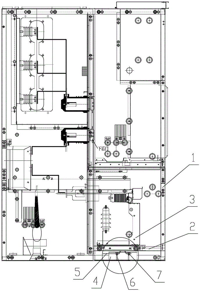
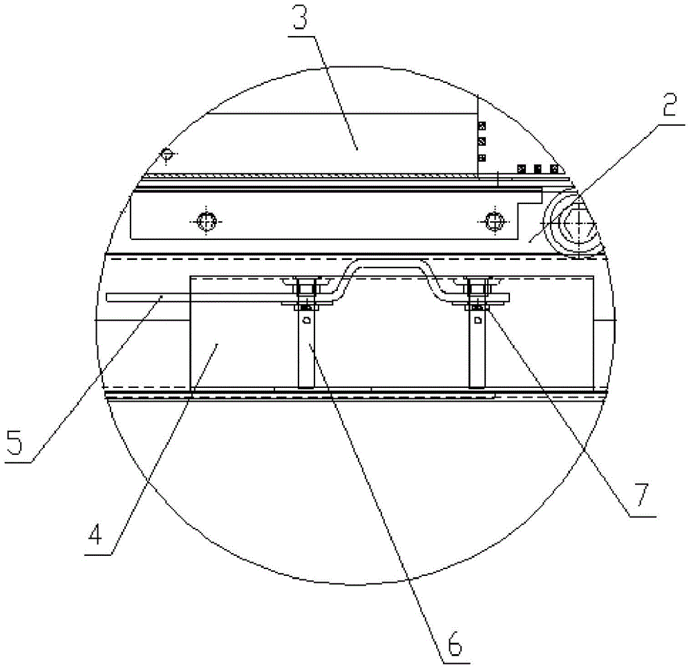
[0041] figure 1 and 2 It is a schematic structural diagram of the electric control cabinet provided in this embodiment. As shown in the figure, the electric control cabinet includes a cabinet body 1 , a handcart guide rail 2 is arranged on the lower part of the cabinet body 1 , and a handcart 3 is arranged on the handcart guide rail 2 . The lower part of the handcart guide rail 2 is provided with an electric control cabinet grounding mounting plate 4, and the grounding mounting plate 4 is fixed on the cabinet body 1. The ground bar 5 of the electric control cabinet is supported by the ground mounting plate 4 of the electric control cabinet so that the ground bar 5 abuts against the guide rail 2 of the handcart.

[0042] like Figures 5 to 7 As shown, the above-mentioned electric control cabinet grounding mounting plate 4 includes a base plate 41, the two sides of the base plate 41 are bent inward at right angles to form a first bending edge 42, and the outer edges of the fi...

Embodiment 2

[0049] The basic structure of the electric control cabinet of this embodiment is the same as that of Embodiment 1, as Figure 8 and 9 As shown, the electric control cabinet includes a cabinet body 1, a handcart guide rail 2 is arranged on the lower part of the cabinet body 1, and a handcart 3 is arranged on the handcart guide rail 2. The lower part of the handcart guide rail 2 is provided with an electric control cabinet grounding mounting plate 4, and the grounding mounting plate 4 is fixed on the cabinet body 1. The ground bar 5 of the electric control cabinet is supported by the ground mounting plate 4 of the electric control cabinet so that the ground bar 5 abuts against the guide rail 2 of the handcart.

[0050] The difference from Embodiment 1 is that a spring 8 is also provided between the grounding bar 5 and the fixing nut 7, and the spring 8 can buffer the movement of the grounding bar 5, making the grounding of the handcart 3 more stable.


PUM


Abstract

The invention discloses a grounding installation plate of an electric control cabinet and an electric control cabinet, which are designed to solve the problems of unsafe use of the existing electric control cabinet and the like. The grounding mounting plate of the electric control cabinet includes a base plate, the two side edges of the base plate are respectively bent inwards and provided with first bending edges, and the outer edges of the first bending edges are respectively bent outwards and provided with second bending edges. Bending edges; the base plate and the first bending edges on both sides enclose an accommodating space for accommodating the grounding bar and the grounding terminal; the base plate has a ground terminal installation hole; the second bending edge There are fixing holes for fixing the grounding mounting plate on the top. At the same time, an electric control cabinet with the grounding mounting plate is proposed. By setting the grounding mounting plate supporting the grounding bar, the grounding bar is in contact with the guide rail of the handcart to realize the grounding of the handcart and effectively protect the safety of operators and carrying instruments.

Description

technical field [0001] The invention relates to a grounding mounting plate of an electric control cabinet and an electric control cabinet provided with the grounding mounting plate. Background technique [0002] Electric control cabinet is to assemble switchgear, measuring instrument, protective device and auxiliary equipment in closed or semiclosed metal cabinet or on screen width according to electrical wiring requirements, and its layout should meet the requirements of normal operation of power system, and is easy to overhaul and does not endanger people. Safety of personal and surrounding equipment. It includes power distribution cabinets, distribution boxes, electrical control cabinets, etc. During normal operation, the circuit can be connected or disconnected by means of manual or automatic switches. Cut off the circuit or alarm with the help of protective electrical appliances in case of failure or abnormal operation. Various parameters in operation can be displayed...

Claims


Application Information

Patent Timeline
Patent Type & Authority Patents(China)
IPC IPC(8): H02B11/28H02B11/167
Inventor 吴存林吴浩
Owner LIUZHOU HAIGE ELECTRICAL
Why Eureka
Try Eureka