
Scintillator panel, radiation detector, and method for manufacturing the same

a technology of radiation detector and scintillator, which is applied in the direction of instruments, conversion screens, nuclear engineering, etc., can solve the problems of insufficient sharpness, insufficient spatial resolution, and the image quality level of the screen-film system has not reached the level of the screen-film system, so as to improve the emission property and improve the sharpness.

Active Publication Date: 2011-08-25
KONICA MINOLTA MEDICAL & GRAPHICS INC
View PDF11 Cites 14 Cited by
  • Summary
  • Abstract
  • Description
  • Claims
  • Application Information

AI Technical Summary

Benefits of technology

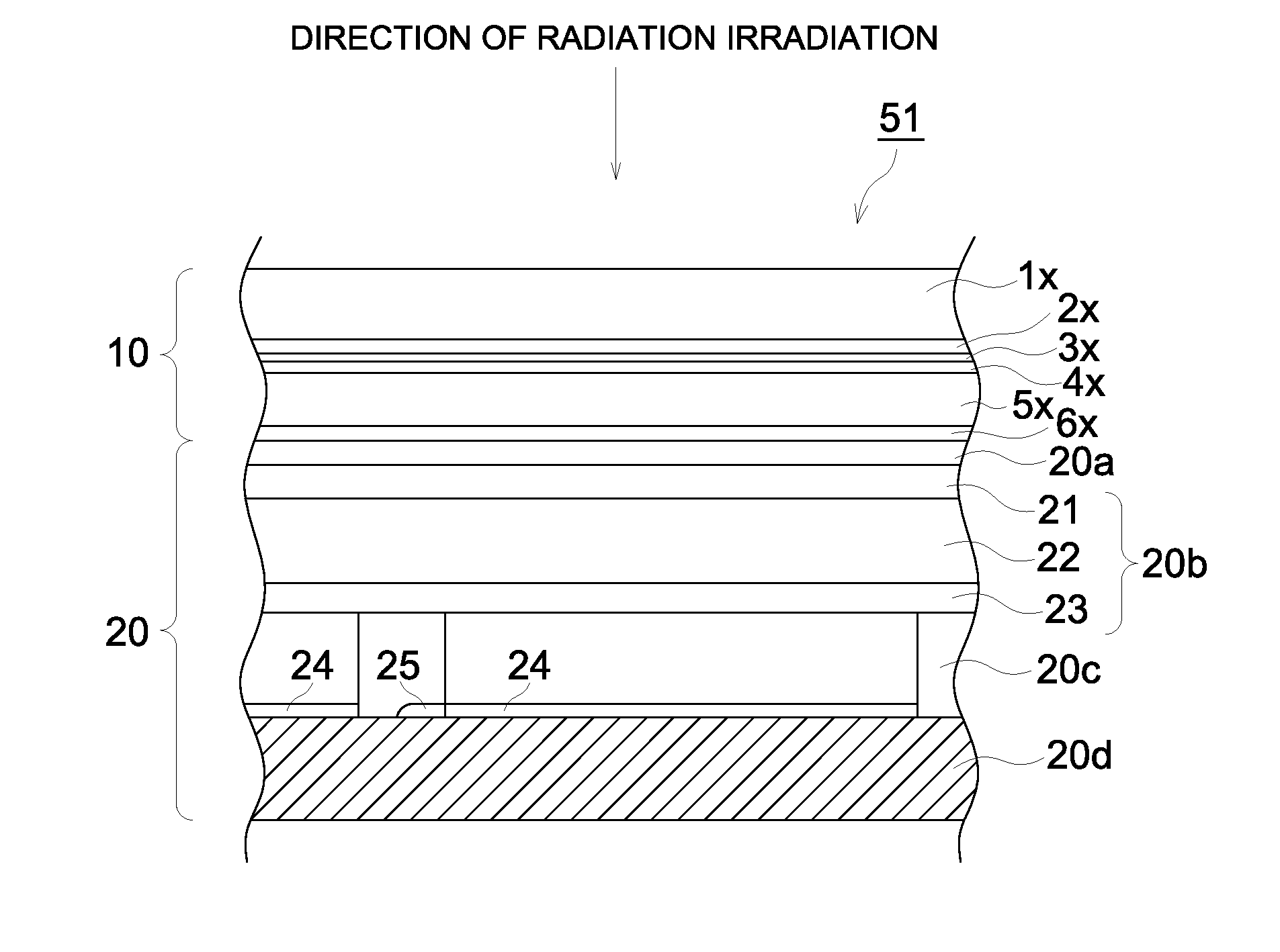
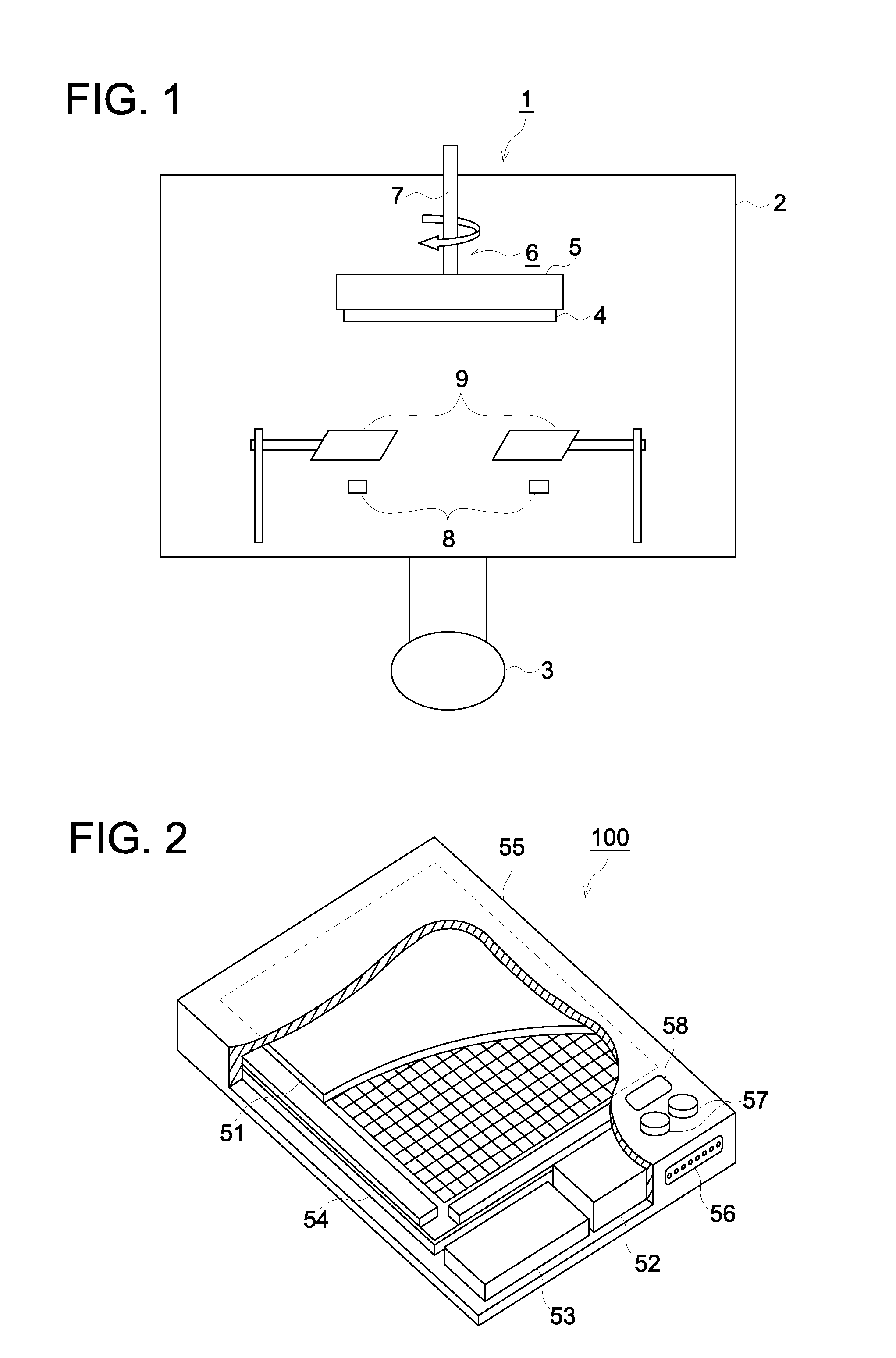
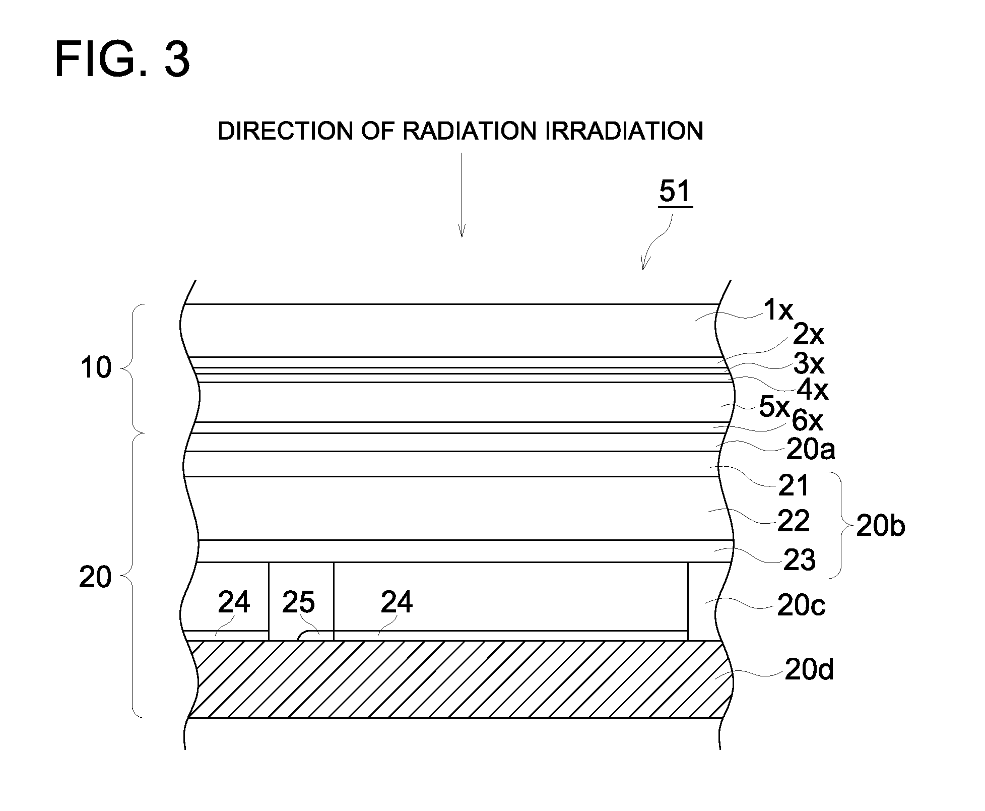
[0023]According to the present invention, a scintillator panel and a radiation detector which gives a radiation image improved in an unevenness of emission property and an unevenness of sharpness and a method for manufacturing the same can be provided.

Problems solved by technology

However, sharpness is insufficient and spatial resolution is also insufficient, whereby its image quality level has not reached that of the screen-film systems.
However, when only CsI is employed, the light emission efficiency is relatively low.
However, as an activator has different crystal structure from cesium iodide, higher concentration of the activator deteriorates sharpness due to distortion of the columnar crystal structure.
Thereby, when unevenness of the activator concentration increases, problems of unevenness occur not only in sensitivity but also in sharpness.
However, this invention substantially relates to a stimulable phosphor, the columnar crystal structure of base phosphor material fuses with a columnar crystal structure of the phosphor in places of the obtained phosphor layer, resulting in rather worse unevenness of sharpness.

Method used


Image

  • Scintillator panel, radiation detector, and method for manufacturing the same
  • Scintillator panel, radiation detector, and method for manufacturing the same
  • Scintillator panel, radiation detector, and method for manufacturing the same

Examples


example 1

[0166]In the preparation of Comparable example 1, the scintillator panel was prepared by changing the phosphor material 1 to only Tl.

example 2

[0167]In the preparation of Example 1, the scintillator panel was prepared except that the phosphor material 2 was divided equally in two vaporization source crucibles, arranged on the same circle and vapor deposited simultaneously.

example 3

[0168]In the preparation of Example 1, the scintillator panel was prepared except that the phosphor material 1 was divided equally in two vaporization source crucibles and vapor deposited and the deposition was completed when the thickness of the phosphor layer came up to 30 μm. After increasing the temperature of the support (substrate) to 200° C., the phosphor material 2 was divided equally in 4 vaporization source crucibles, arranged on the same circle and vapor deposited simultaneously and the deposition was completed when the thickness of the phosphor layer came up to 450 μm. Consequently, the phosphor layer was put into the protective layer bag to obtain the scintillator panel having the structure of sealed phosphor layer.


PUM

PropertyMeasurementUnit
temperatureaaaaaaaaaa
light emission wavelengthaaaaaaaaaa
melting pointaaaaaaaaaa

Abstract

Provided are a scintillator panel and a radiation detector which give a radiation image reduced in sensitivity unevenness and sharpness unevenness. Also provided are processes for producing the scintillator and the detector. The scintillator panel comprises a support and, deposited thereon, a phosphor layer comprising columnar crystals of a phosphor which have been formed by the vapor deposition method. The panel is characterized in that the columnar crystals of a phosphor comprise cesium iodide (CsI) as a base ingredient and thallium (Tl) as an activator ingredient and have, in a root part thereof, a layer containing no thallium, and that the coefficient of variation in thallium concentration in the plane of the phosphor layer is 40% or less.

Description

TECHNICAL FIELD[0001]The present invention relates to a scintillator panel and a radiation detector which gives a radiation image improved in an unevenness of emission property and an unevenness of sharpness and a method for manufacturing the same.BACKGROUND[0002]Heretofore, radiation images such as X-ray images have widely been employed in hospitals and clinics for the state of a disease. Specifically, over a long period of history, radiation images formed via intensifying screen-film systems have resulted in high photographic speed and high image quality, whereby even now, they are employed in hospitals and clinics in the world as imaging systems which simultaneously exhibit high reliability and cost performance.[0003]However, types of the above image information are those of so-called analogue image information, and enable to achieve neither free image processing nor instantaneous electric transmission, which is realized in digital image information which has been developed in re...

Claims


Application Information

Patent Timeline
Patent Type & Authority Applications(United States)
IPC IPC(8): G01T1/20C23C16/22B05D5/06
CPCC09K11/628G21K4/00C23C14/0694
Inventor KASAI, SHIGETAMIISA, HIROSHIIIJIMA, MAKOTONAGATA, YASUSHI
Owner KONICA MINOLTA MEDICAL & GRAPHICS INC
Learn More