Male bayonet connector

a bayonet connector and male technology, applied in the field of medical devices, can solve the problems of unwanted disconnection, leakage of existing tubing connectors, etc., and achieve the effect of facilitating shaft gripping

Active Publication Date: 2011-08-25
GENERAL ELECTRIC CO
View PDF50 Cites 75 Cited by
  • Summary
  • Abstract
  • Description
  • Claims
  • Application Information

AI Technical Summary

Benefits of technology

[0010]A male bayonet connector may include a shaft defining a lumen therethrough and a grip that facilitates gripping of the shaft by the user. The outer surface of the shaft may define a tubing coupling for connecting with a section of tubing, an annular recess or channel that interfaces with a

Problems solved by technology

Existing tubing connectors are prone to leakage and unwanted disconnection when the patient is still receiving treatment via the connected tubes due to

Method used


Image

  • Male bayonet connector
  • Male bayonet connector
  • Male bayonet connector

Examples


Embodiment Construction

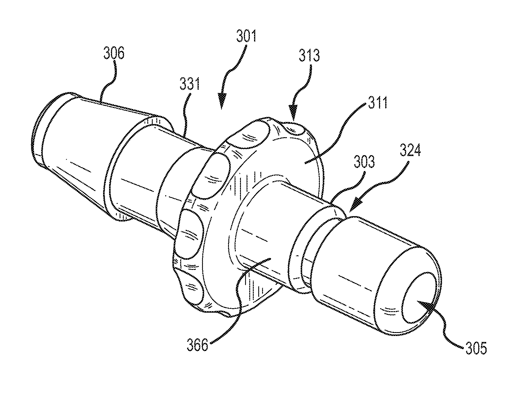
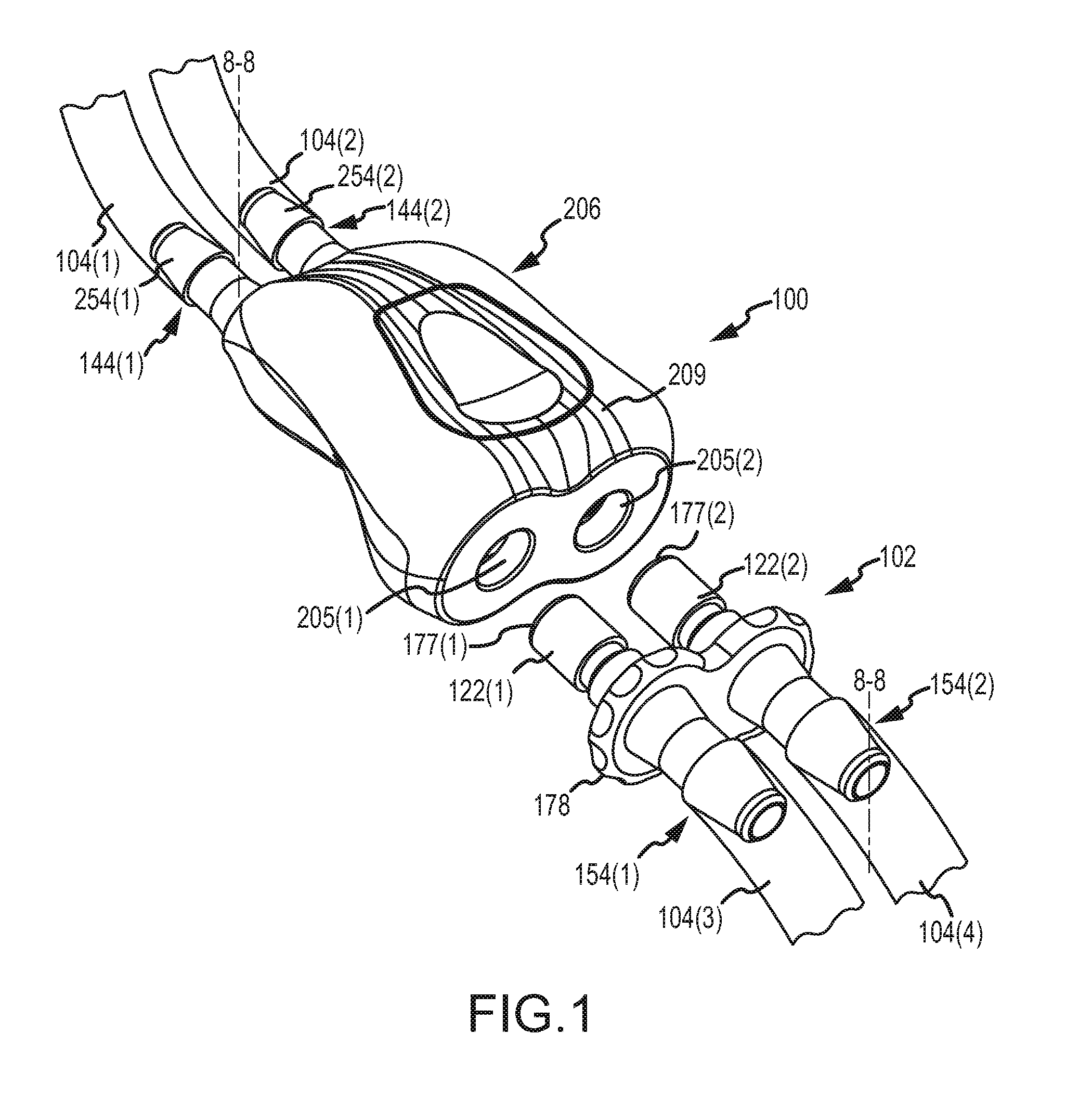
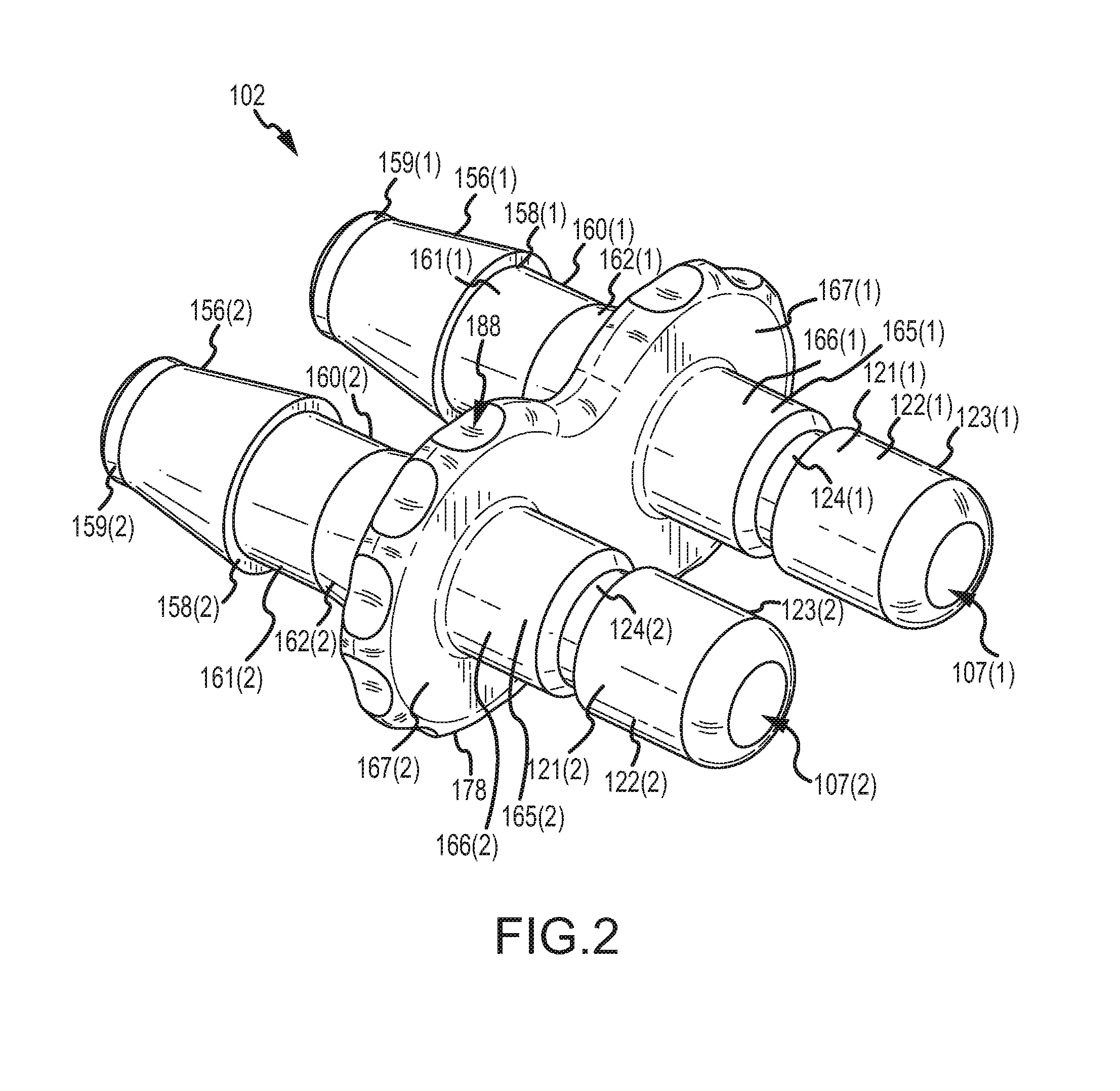
[0032]Male bayonet connectors, in conjunction with female latch connectors, may be used to releasably connect sections of tubing. In one embodiment, the male bayonet connector may have a single shaft portion defining a single lumen therethrough and an outer sealing surface that is configured to engage an inner surface of a female latch connector to form a gas and / or liquid fluid seal between the male and female components. The female latch connector may include a latching mechanism that engages a portion of the male bayonet connector so as to prevent removal of the male bayonet connector when connected with the female connector. In another embodiment, the male bayonet connector may have dual shafts, each defining a lumen therethrough. In alternative embodiments, the male bayonet connector may have three or more shafts defining three or more lumen. In embodiments of multiple lumen male bayonet connectors, a grip portion may be used to join the shaft portions, as well as tubing coupli...


PUM


Abstract

A male bayonet connector connects a section of tubing to a female latch connector. The male bayonet connector includes a shaft defining a lumen, a distal end portion, and a proximal end portion. The distal end portion of the shaft has a sealing surface configured to engage a seal member within the female latch connector to create a fluid-tight seal. The shaft defines an annular recess proximal to and adjacent the distal end portion. The annular recess has a proximal chamfered sidewall and a distal sidewall perpendicular to the axis of the lumen, which are separated by a band of smaller diameter than the sealing surface. A grip is formed on the make bayonet connector between the proximal end portion and the annular recess. A ratio of a length of the first sealing surface to a distance between the grip and the distal sidewall is such that a side-load force, as imparted on the male bayonet connector, will not break a fluid-tight seal between the sealing surface and the seal member.

Description

CROSS REFERENCE TO RELATED APPLICATIONS[0001]This application claims the benefit of priority pursuant to 35 U.S.C. §119(e) of U.S. provisional application No. 61 / 289,545 filed 23 Dec. 2009 entitled “Male bayonet connector,” which is hereby incorporated herein by reference in its entirety. This application is a continuation-in-part of U.S. design patent application Ser. No. 29 / 351,665 filed 9 Dec. 2009 entitled “Male dual lumen bayonet connector,” which is hereby incorporated herein by reference in its entirety.[0002]The present application is related to U.S. patent application Ser. No. ______ [Attorney Docket No. P191622.US.03] filed contemporaneously herewith entitled “Fluid connector latches profile lead-ins”; U.S. patent application Ser. No. ______ [Attorney Docket No. P191627.US.03] filed contemporaneously herewith entitled “Button latch with integrally molded cantilever springs”; and U.S. design patent application no. 29 / 352,637 filed 23 Dec. 2009 entitled “Female dual lumen co...

Claims


Application Information

Patent Timeline
IPC IPC(8): F16L37/00
CPCF16L37/0841F16L37/56A61M39/1011A61M2039/1088A61M2039/1027A61M2039/1044A61M2039/1083A61M39/105A61B5/02141A61B5/02233A61B2562/225
Inventor LEWIS, PETER D.NARAYANAN, RAVIKUMARCAIRNS, RICHARD W.PHIPPS, RILEY M.
Owner GENERAL ELECTRIC CO
Why Eureka
Try Eureka