
High resolution imaging devices with wide field and extended focus

Active Publication Date: 2011-08-25
CALIFORNIA INST OF TECH
View PDF65 Cites 30 Cited by
  • Summary
  • Abstract
  • Description
  • Claims
  • Application Information

AI Technical Summary

Benefits of technology

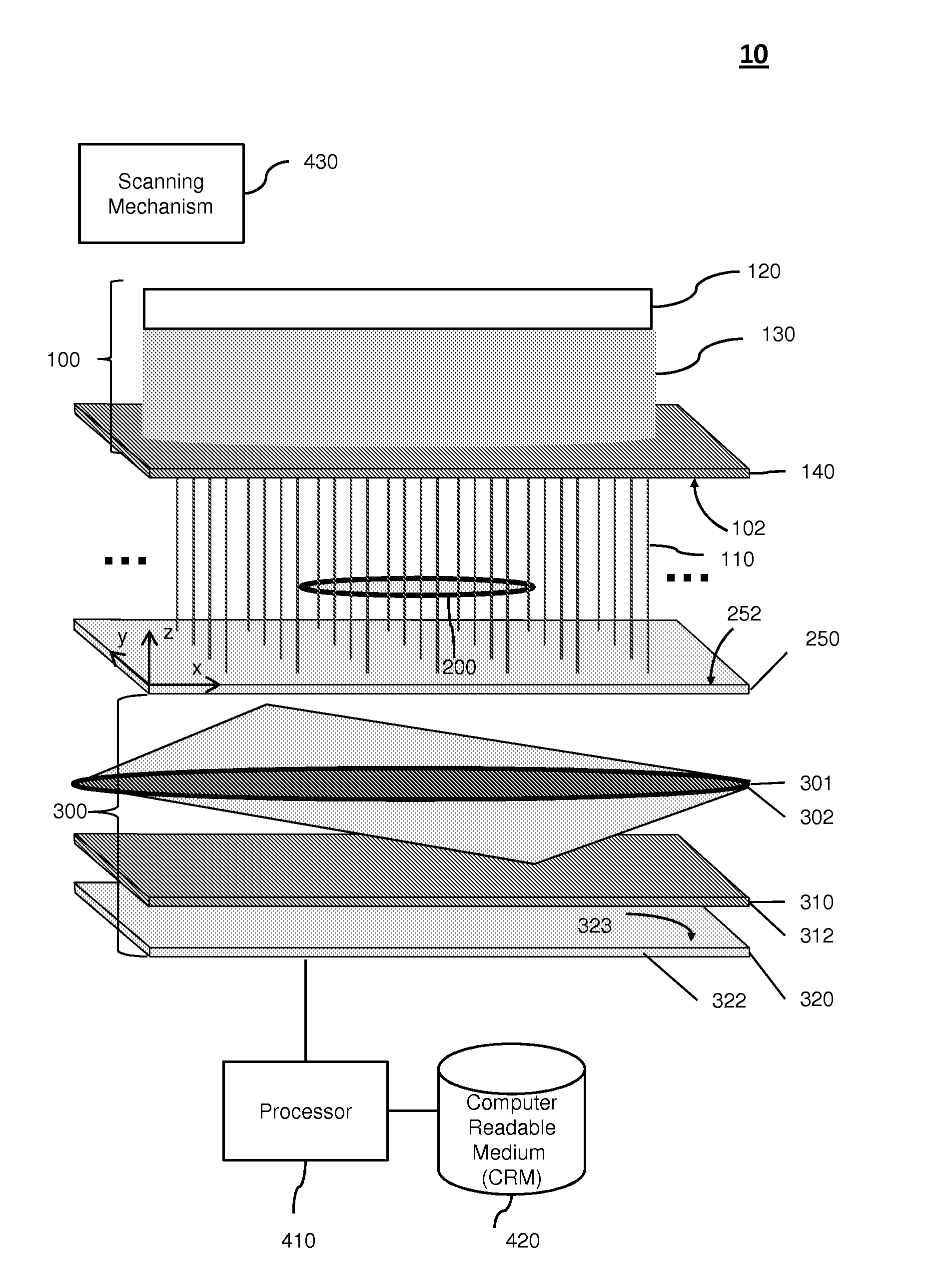
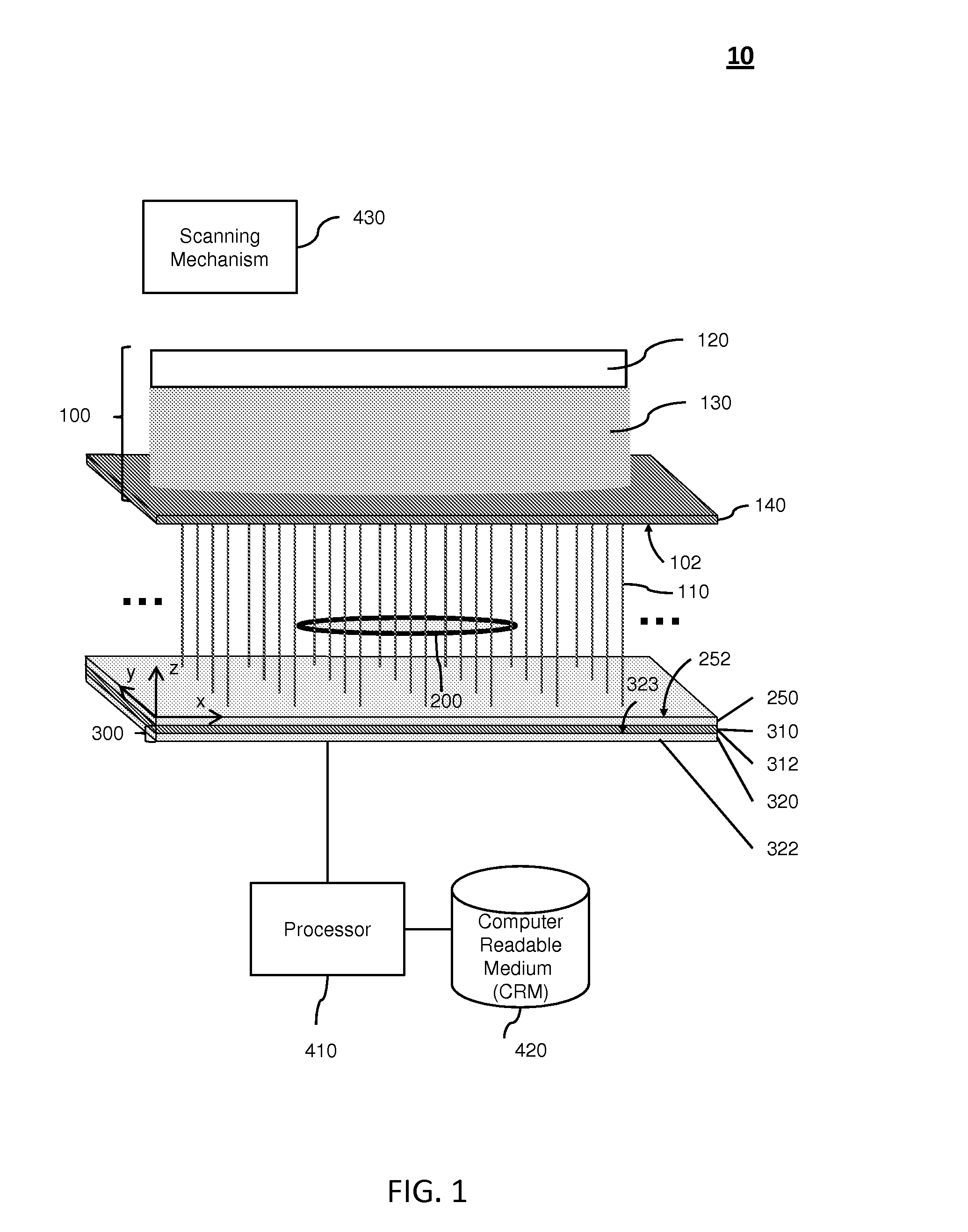
[0007]Embodiments of the present invention relate to a high resolution imaging device with wide field and extended focus (HRID) that can generate high resolution two-dimensional images of thick sample volumes. The HRID uses a plurality of nondiffracting beams (e.g., Bessel beams) that can propagate through the extended depth of a thick sample volume having an object being imaged. The HRID illuminates the sample volume by scanning the nondiffracting beams through the sample volume or moving the sample through the nondiffracting beams. The HRID images the object in the sample on a light detector (e.g., photosensor) directly (direct imaging) or with an inexpensive lens projecting images onto the light detector (projection imaging). In this way, the HRID can acquire two-dimensional images over large areas of the sample, while promptly showing intricate high resolution details, even those that are well outside the focal plane of traditional microscopes. The HRID has an extended focal range due to the relatively long length of the nondiffracting beams compared to the depth of field in traditional microscopes.

Problems solved by technology

Despite being mature tools, conventional optical microscopes do not have the ability to acquire high resolution images of large sample volumes.
This inability is the consequence of a tradeoff between a conventional microscope's resolution, its field of view, and its depth of field.
In conventional microscopes, any attempt to increase resolution fundamentally results in a decrease in the depth of field, and for practical purposes decreases the field of view.
Conventional microscopes are therefore restricted to acquire either low resolution images of large sample volumes, or high resolution images of small sample volumes.

Method used


Image

  • High resolution imaging devices with wide field and extended focus
  • High resolution imaging devices with wide field and extended focus
  • High resolution imaging devices with wide field and extended focus

Examples


Embodiment Construction

[0020]Embodiments of the present invention will be described below with reference to the accompanying drawings. The HRID has a beam generator that can create a plurality of nondiffracting beams (e.g., series of Bessel beams) that propagate through the thickness of a sample (extended depth of field) having an object being imaged. A scanning mechanism is used to illuminate a sample volume with the object. The scanning mechanism either scans the nondiffracting beams (e.g., Bessel beams) through the sample volume or moves the sample volume through the nondiffracting beams. By using the scanning mechanism, the HRID can illuminate a thick sample over a large area (wide field of view). The HRID then images the object directly onto a light detector (direct imaging) or projects with a lens onto the light detector (projection imaging). In this way, the HRID can acquire two-dimensional images of large areas, while promptly showing intricate high resolution details, even those that are well out...


PUM


Abstract

Embodiments of the present invention relate to a high-resolution imaging device with wide field and extended focus comprising a beam generator for generating a plurality of nondiffracting beams and a scanning mechanism for moving the plurality of nondiffracting beams relative to the object to illuminate a volume of the object. The high-resolution imaging device also comprises surface element and a body having a light detector layer outside the surface element. The light detector layer has a light detector configured to measure light data associated with the plurality of nondiffracting beams illuminating the volume of the object. In some cases, the high-resolution imaging device also includes a lens inside of the light detector layer. The lens is configured to focus the light on the light detector surface.

Description

CROSS-REFERENCES TO RELATED APPLICATIONS[0001]This is a non-provisional application of, and claims priority to, U.S. Provisional Patent Application No. 61 / 307,324 entitled “Three Dimensional Imaging with Optofluidic Microscopes” filed on Feb. 23, 2010 and U.S. Provisional Patent Application No. 61 / 307,328 entitled “High-Resolution Microscopy with a Wide Field and Extended Focus” filed on Feb. 23, 2010. These provisional applications are hereby incorporated by reference in their entirety for all purposes.[0002]This non-provisional application is related to the following co-pending and commonly-assigned patent applications, which are hereby incorporated by reference in their entirety for all purposes:[0003]U.S. patent application Ser. No. 13 / 032,449 entitled “Nondiffracting Beam Detection Devices for Three-Dimensional Imaging” filed on Feb. 22, 2011.BACKGROUND OF THE INVENTION[0004]Embodiments of the present invention generally relate to imaging devices. More specifically, certain emb...

Claims


Application Information

Patent Timeline
IPC IPC(8): H04N7/18H04N13/221
CPCG02B21/16G02B21/361G02B27/2242H04N13/0253H04N13/0207H04N13/0221G02B27/2285H04N13/221H04N13/207H04N13/254G02B30/54G02B30/36
Inventor PAVANI, SRI RAMA PRASANNAYANG, CHANGHUEIWU, JIGANG
Owner CALIFORNIA INST OF TECH
Learn More