
Tag sensor system and sensor device, and object position estimating device and object position estimating method

a technology of sensor system and object position estimation, which is applied in the field of position identification system, can solve the problems of inability to specify, inability to image the monitoring target with the security camera, and inability to acquire camera positioning data, etc., and achieve the effect of reliably keeping track of the monitoring target, suppressing the power consumption of the radio communication terminal, and improving monitoring accuracy

Inactive Publication Date: 2011-08-25
PANASONIC CORP
View PDF0 Cites 50 Cited by
  • Summary
  • Abstract
  • Description
  • Claims
  • Application Information

AI Technical Summary

Benefits of technology

[0014]The present invention has been accomplished under the above-described circumstances, and an object of the present invention is to provide a position identifying system capable of improving monitoring accuracy and reliably keeping track of a monitoring target using positioning information based on radio communication, even if positioning based on a picked-up image fails, while suppressing the power consumption of a radio communication terminal, such as an active tag.
[0015]In addition, the present invention has been accomplished under the above-described circumstances, and another object of the present invention is to provide an object position estimating device and an object position estimating method capable of improving position estimating accuracy in a case where the position of a target is estimated using probability density distributions.Means for Solving the Problems

Problems solved by technology

However, in the conventional system, there may be a case that, for example, a monitoring target enters a dead angle of the security camera and, therefore, the monitoring target cannot be imaged with the security camera and camera positioning data cannot be acquired.
Thus, the system has not been able to specify the position of the monitoring target within an image and has had difficulty in keeping track of the movement of the monitoring target.
As a result, position estimating accuracy is also degraded.

Method used


Image

  • Tag sensor system and sensor device, and object position estimating device and object position estimating method
  • Tag sensor system and sensor device, and object position estimating device and object position estimating method
  • Tag sensor system and sensor device, and object position estimating device and object position estimating method

Examples


modified example 1

(Modified Example 1 of Position Identifying System of Another Embodiment)

[0202]FIG. 15 a block diagram illustrating the configuration of modified example 1 of a position identifying system of another embodiment. Also here, an explanation will be made with a focus on the configuration and operation in which modified example 1 differs from other embodiments. That is, unless otherwise referred to here, the configuration and operation of modified example 1 are the same as those of the above-described other embodiments.

[0203]A position identifying unit 17 of modified example 1 is provided with not only an image position local search unit 29 but also a tag position local search unit 35 for exploring whether or not any tag positions exist within a circular area (search area) having a predetermined radius and centered on a tag position. Tag positions and image positions at a certain time are input to the tag position local search unit 35, and processing is performed in order to search for a...

modified example 2

(Modified Example 2 of Position Identifying System of Another Embodiment)

[0208]FIG. 16 a block diagram illustrating the configuration of modified example 2 of a position identifying system of another embodiment. Also here, an explanation will be made with a focus on the configuration and operation in which modified example 2 differs from other embodiments. That is, unless otherwise referred to here, the configuration and operation of modified example 2 are the same as those of the above-described other embodiments.

[0209]A position identifying unit 17 of modified example 2 is provided with a combinational calculation unit 38 for calculating a combination in which a square sum of differences in distance between an image position and a tag position is minimum, in place of the image position local search unit 29. Tag positions and image positions at a certain time are input to this combinational calculation unit 38 to calculate the optimum combination of those tag positions and image po...

modified example 3

(Modified Example 3 of Position Identifying System of Another Embodiment)

[0211]FIG. 17 a block diagram illustrating the configuration of modified example 3 of a position identifying system of another embodiment. Also here, an explanation will be made with a focus on the configuration and operation in which modified example 3 differs from other embodiments. That is, unless otherwise referred to here, the configuration and operation of modified example 3 are the same as those of the above-described other embodiments.

[0212]A position identifying unit 17 of modified example 3 is provided with an average value calculation unit 39 for calculating an average position of correlated image positions and tag positions as the position of a monitoring target. The positioning accuracies of image positioning and radio positioning are input to this average value calculation unit 39. Then, using Expression 3 shown below, a weighted average according to the positioning accuracies is calculated as an ...


PUM


Abstract

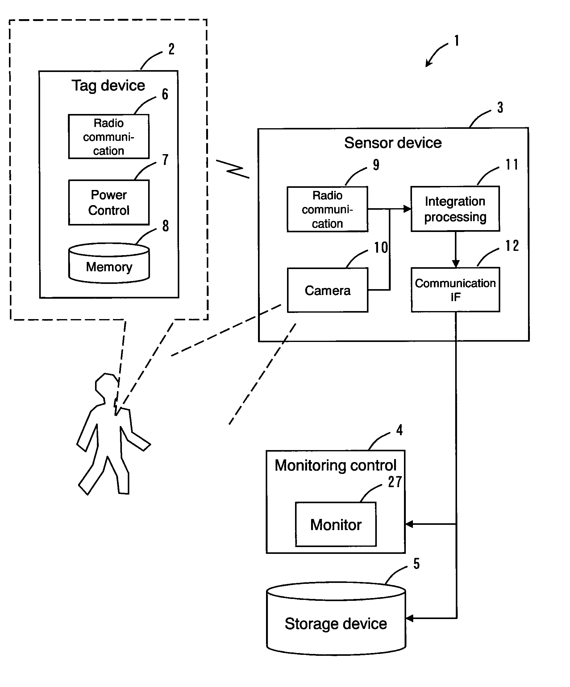
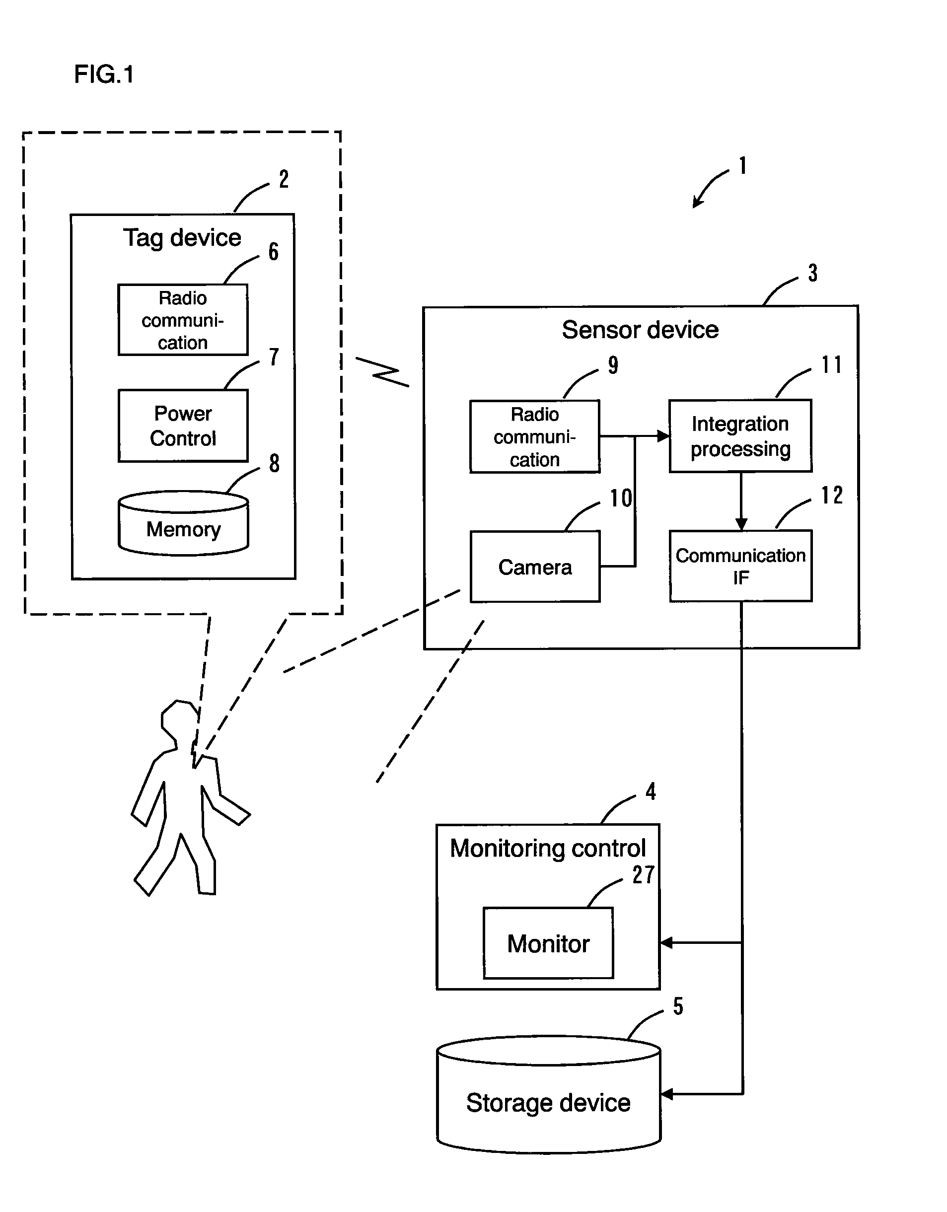
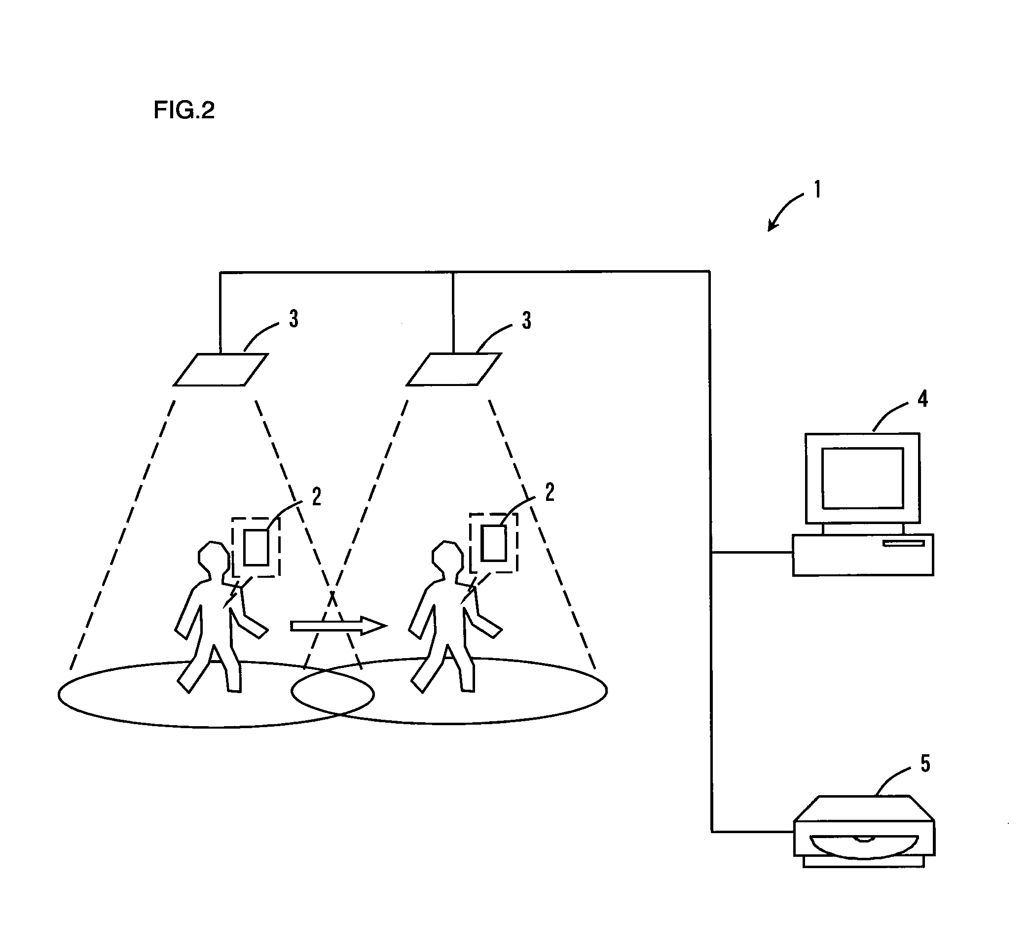
A position identifying system (1) is comprised of a radio terminal device (2) carried by a monitoring target and a sensor device (3) provided with a radio communication unit (9) for communicating by radio with the radio terminal device (2) and a camera unit (10) for taking an image of the monitoring target. In the sensor device (3), the position (tag position) of the radio terminal device (2) is detected on the basis of a detection signal from the radio terminal device (2), and the position (image position) of the monitoring target is calculated on the basis of the image taken by the camera unit (3). By linking the tag position with the image position, the position of the monitoring target is identified. Thus, there is provided the position identifying system capable of identifying the position of the monitoring target and keeping track of the movement of the monitoring target even if the image of the monitoring target cannot be taken.

Description

TECHNICAL FIELD[0001]The present invention relates to a position identifying system provided with a radio terminal device and a sensor device and, more particularly, to a technique to identify the position of a monitoring target by means of radio communication with the radio terminal device and using a picked-up image of the monitoring target. The present invention also relates to an object position estimating device and an object position estimating method for estimating the position of a target on the basis of the probability density of positioning coordinates.BACKGROUND ART[0002]Conventionally, there has been known a position sensing system that uses an RFID positioning device and a security camera. For example, Japanese Patent Laid-Open No. 2006-311111 discloses such a system as described above. In this conventional system, an authenticator has an active tag. The authenticator takes an image of an area being monitored using a security camera and detects the active tag using an R...

Claims


Application Information

Patent Timeline
IPC IPC(8): H04N7/18
CPCG01S19/23
Inventor AOTA, KAZUYUKIKIMURA, YASUNARIMORIOKA, MIKIOSUGIURA, MASATAKAUEDA, JUNKOMUKAI, ARATA
Owner PANASONIC CORP
Learn More