Three-dimensional image display apparatus and method of adjusting displayed image

a display apparatus and three-dimensional image technology, applied in the direction of optics, electrical equipment, instruments, etc., can solve the problems of not adjusting the position of the image combiner with respect to the observer, the observer finds it difficult to see the three-dimensional image, and conventional display adjusting techniques fail to solve the above problem

Inactive Publication Date: 2011-08-25
FUJIFILM CORP
View PDF4 Cites 0 Cited by
  • Summary
  • Abstract
  • Description
  • Claims
  • Application Information

AI Technical Summary

Benefits of technology

[0012]With the present invention, the observer can use the position adjusting mechanism to adjust the position of the image combiner with respect to the observer for adjusting a blur in the grid-like combined image due to a positional deviation between the right-eye image and the left-eye image. Each time the posture of the observer who views a three-dimensional image is changed, the observer may use the position adjusting mechanism to adjust the position of the image combiner until the blur in the grid-like combined image is minimized. Accordingly, the position of the image combiner can be adjusted appropriately.
[0013]Since the right-eye image and the left-eye image are essentially identical grid-like images, if there is no positional deviation between the right-eye image and the left-eye image, then the grid-like combined image which is generated by combining the right-eye image and the left-eye image is a sharp image free of blurs. By directly viewing the sharp combined image, therefore, the observer can easily judge that it is not necessary to adjust the position of the half-silvered mirror using the position adjusting mechanism.
[0015]According to the present invention, therefore, even when the observer changes its posture, the observer can adjust the image combiner to its appropriate position and hence can view a sharp three-dimensional image.
[0018]Since the width of the groove is greater than the thickness of the half-silvered mirror, the width provides a position adjusting range in which the half-silvered mirror is positionally adjustable. The position adjusting members make it possible to finely adjust the position of the half-silvered mirror in the position adjusting range along the thickness of the half-silvered mirror.
[0020]The frame may have threaded holes defined therein which are open to the groove in a direction along the thickness of the half-silvered mirror. The position adjusting members may comprise screws, respectively, threaded in the threaded holes, respectively, and having respective tip ends held in contact with the peripheral edges of the half-silvered mirror. Therefore, the position of the half-silvered mirror can easily be adjusted minutely along the thickness of the half-silvered mirror.
[0021]If the grid-like combined image is blurred in a portion thereof, then those of the position adjusting members which are close to a portion of the half-silvered mirror that corresponds to the blurred portion of the grid-like combined image may be used to positionally adjust the half-silvered mirror. Inasmuch as the position of the half-silvered mirror can be adjusted locally, the position of the half-silvered mirror can be adjusted precisely and accurately.

Problems solved by technology

If the observer who views the three-dimensional image changes its posture, then the observer finds it difficult to see the three-dimensional image.
However, the display adjusting techniques disclosed in the above publications do not adjust the position of the image combiner with respect to the observer when the posture of the observer with respect to the three-dimensional image changes.
Therefore, the conventional display adjusting techniques fail to solve the above problem even if they are applied to three-dimensional image display apparatus.

Method used


Image

  • Three-dimensional image display apparatus and method of adjusting displayed image
  • Three-dimensional image display apparatus and method of adjusting displayed image
  • Three-dimensional image display apparatus and method of adjusting displayed image

Examples


Embodiment Construction

[0038]A three-dimensional image display apparatus according to an embodiment of the present invention and a method of adjusting a combined image that is displayed by the three-dimensional image display apparatus will be described below with reference to FIGS. 1 through 13.

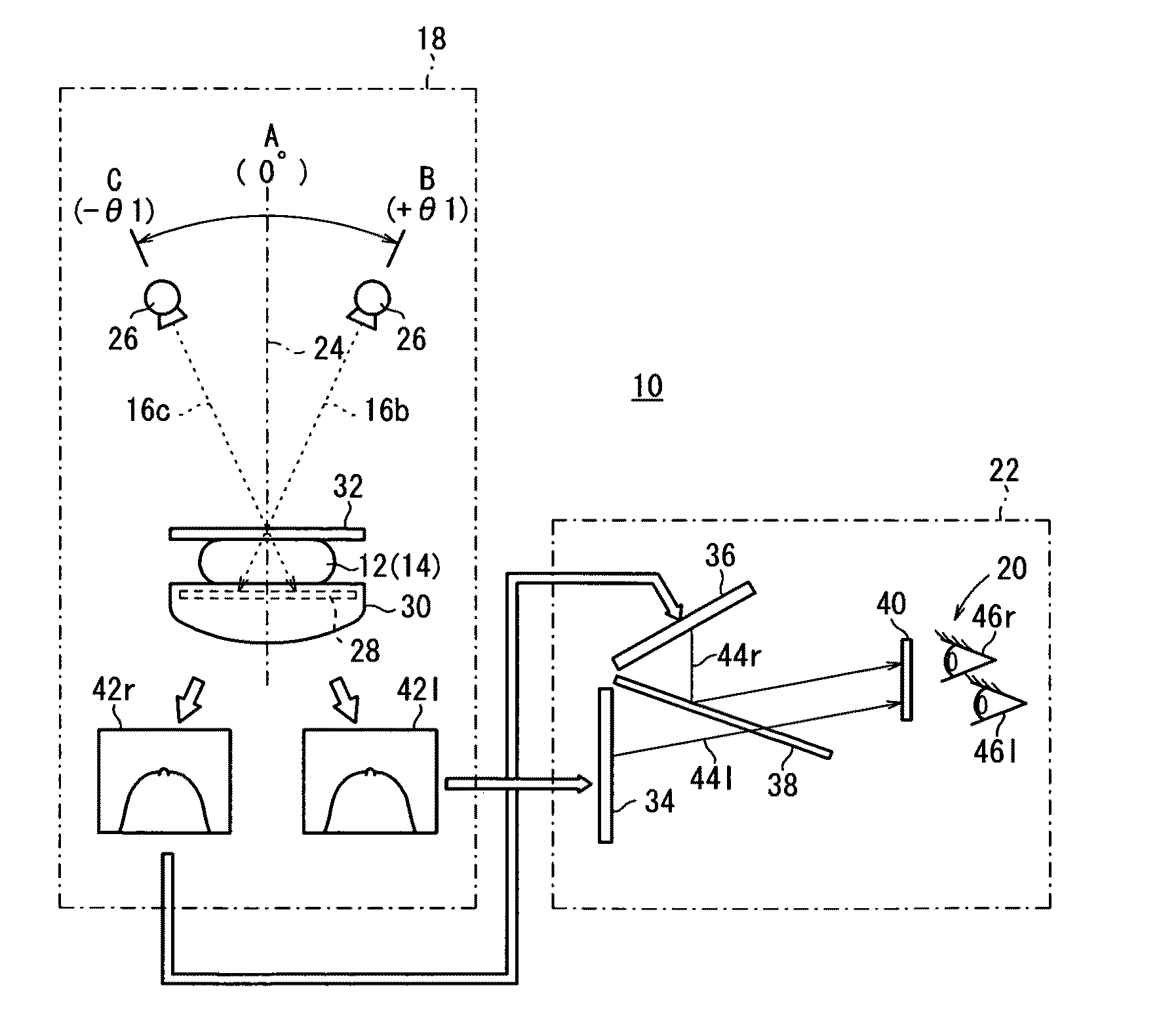
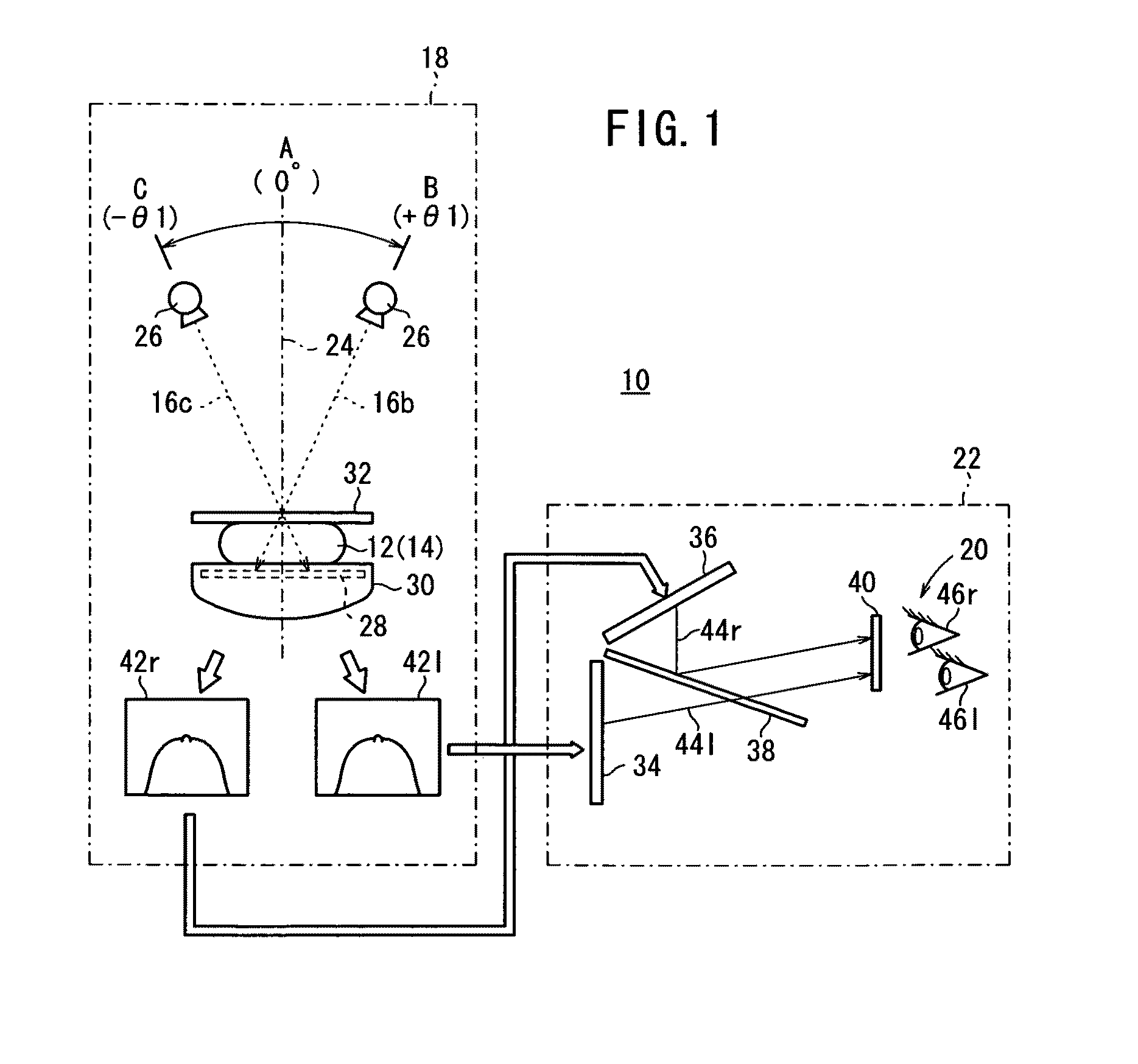
[0039]First, a radiographic image capturing system 10 incorporating a three-dimensional image display apparatus 22 according to an embodiment of the present invention will be described below with reference to FIG. 1.

[0040]As shown in FIG. 1, the radiographic image capturing system 10 basically comprises a mammographic apparatus 18 for performing a stereographic image capturing process to apply radiation 16b, 16c at different angles to a breast 14 of a subject 12 for thereby acquiring two radiographic images each representing the breast 14, and the three-dimensional image display apparatus 22 for enabling an observer 20, such as a doctor, a radiological technician, or the like, to view a three-dimensional image base...


PUM


Abstract

A three-dimensional image display apparatus includes an image combiner which combines a grid-like right-eye image and a grid-like left-eye image, which are substantially identical to each other, into a grid-like combined image, and a position adjusting mechanism which adjusts a position of the image combiner with respect to an observer to adjust a blur in the grid-like combined image due to a positional deviation between the grid-like right-eye image and the grid-like left-eye image.

Description

CROSS-REFERENCE TO RELATED APPLICATION[0001]This application is based upon and claims the benefit of priority from Japanese Patent Application No. 2010-038595 filed on Feb. 24, 2010, of which the contents are incorporated herein by reference.BACKGROUND OF THE INVENTION[0002]1. Field of the Invention[0003]The present invention relates to a three-dimensional image display apparatus for enabling an observer to view a three-dimensional image based on a combined image which is produced by combining a two-dimensional image (right-eye image) to be seen by the right eye of the observer and a two-dimensional image (left-eye image) to be seen by the left eye of the observer, and a method of adjusting the combined image that is displayed.[0004]2. Description of the Related Art[0005]Heretofore, there has been known in the art a three-dimensional image display apparatus for enabling an observer to view, as a three-dimensional image, a combined image using a stereoscope by displaying a two-dimens...

Claims


Application Information

Patent Timeline
Patent Type & Authority Applications(United States)
IPC IPC(8): G02B27/22G02B30/25G02B30/60
CPCG02B27/2235H04N13/0497H04N13/0434G02B27/26G02B30/25G02B30/35H04N13/337H04N13/398
Inventor YOSHIKAWA, KENJI
Owner FUJIFILM CORP
Why Eureka
Try Eureka