Storage control device, storage device and storage device system

a storage device and control device technology, applied in the field of storage control devices, storage devices and storage devices systems, can solve the problem of requiring an increased number of wires, and achieve the effect of simplifying the wiring structur

Inactive Publication Date: 2011-08-25
SONY CORP
View PDF17 Cites 25 Cited by
  • Summary
  • Abstract
  • Description
  • Claims
  • Application Information

AI Technical Summary

Benefits of technology

[0014]Still further, in the first mode, an electrode adapted to receive the selected temperature information from the storage control device at the previous stage may be provided on the top surface of the storage control device of interest and located at the same position as an electrode adapted to output the selected temperature information. This electrode is provided on the bottom surface of the storage control device at the previous stage that is located above and adjacent to the storage control device of interest when the storage control device of interest and other storage control devices are stacked one on top of the others. This provides an advantageous effect in that, when storage control devices are stacked one on top of the others, the selected temperature information is received through junction between the electrodes, one on the storage control device of interest and another on the storage control device located thereabove that corresponds to the storage control device at the previous stage.
[0015]Still further, in the first mode, an electrode adapted to receive or output the integrated temperature information may include a penetrating electrode and be located at the same position as penetrating electrodes provided on other storage control devices as part of a signal path of the integrated temperature information when the storage control device of interest and the other storage control devices are stacked one on top of the others. This provides an advantageous effect in that, when storage control devices are stacked one on top of the others, the signal path of the integrated temperature information is shared between the upper and lower storage control devices through junction between the electrodes.
[0016]Further, a second mode of the present invention is a storage device that includes a memory array, temperature sensor, temperature information selection section, refresh command reception section and trigger issuance frequency setting section. The temperature sensor detects the temperature condition to generate own temperature information. The temperature information selection section selects, based on the temperature condition indicated by selected temperature information supplied from a storage device at the previous stage and the temperature condition indicated by the own temperature information, either the supplied selected temperature information or own temperature information. The temperature information selection section outputs the selected external output temperature information or own temperature information to a storage device at the next stage as selected temperature information. The refresh command reception section receives a refresh command whose transmission frequency is set according to the temperature condition indicated by integrated temperature information, i.e., selected temperature information obtained by a storage device at the final stage. The trigger issuance frequency setting section sets, in response to the reception of the refresh command, a refresh trigger issuance frequency based on the integrated temperature information supplied from the storage device at the final stage and the own temperature information. The refresh trigger causes the memory array to perform a refresh. This provides an advantageous effect in that, in order for a storage device to output temperature information, a signal path is formed that is adapted to output selected temperature information to the storage device at the next stage.
[0017]Further, a third mode of the present invention is a storage device system that includes a plurality of storage devices stacked one on top of the others. Each of the storage devices includes a memory array, temperature sensor, temperature information selection section, refresh command reception section, trigger issuance frequency setting section, selected temperature information output electrode, selected temperature information input electrode and integrated temperature information electrode. The temperature sensor detects the temperature condition to generate own temperature information. The temperature information selection section outputs the own temperature information in the absence of a previous stage storage device at the previous stage of and adjacent to the storage device of interest. In the presence of the previous stage storage device, the temperature information selection section selects, based on the temperature condition indicated by selected temperature information supplied from the previous stage storage device and the temperature condition indicated by the own temperature information, either the supplied selected temperature information or own temperature information. The temperature information selection section outputs the selected external output temperature information or own temperature information to a lower storage device located below and adjacent to the storage device of interest or refresh control device as selected temperature information. The refresh command reception section receives a refresh command whose transmission frequency is set according to the temperature condition indicated by integrated temperature information, i.e., selected temperature information obtained by a lowermost storage control device. The trigger issuance frequency setting section sets, in response to the reception of the refresh command, a refresh trigger issuance frequency based on the integrated temperature information supplied from the storage control device at the final stage and the own temperature information. The refresh trigger causes the memory array to perform a refresh. The selected temperature information output electrode is provided on the bottom surface of the storage device of interest to output the selected temperature information to the lower storage device. This electrode is located at the same position as an electrode provided on the top surface of the lower storage device and adapted to receive the selected temperature information. The selected temperature information input electrode is provided on the top surface of the storage device of interest to receive the selected temperature information from the storage device at the previous stage. This electrode is located at the same position as an electrode provided on the bottom surface of the upper storage device and adapted to output the selected temperature information. The integrated temperature information electrode includes a penetrating electrode adapted to receive or output the integrated temperature information. This electrode is located at the same position as penetrating electrodes provided on other storage devices as part of a signal path of the integrated temperature information. This provides an advantageous effect in that two signal paths, one adapted to receive or output the selected temperature information between the upper and lower storage devices, and another of the integrated temperature information, are formed through junction between the electrodes on the chip surfaces of the two storage devices. This provides another advantageous effect in that the signal path of the integrated temperature information is shared between the storage devices.
[0018]Further, a fourth mode of the present invention is a storage device system that includes a plurality of storage devices and a refresh control device all in a chip form, stacked one on top of the others. Each of the storage devices includes a memory array, temperature sensor, temperature information selection section, refresh command reception section, trigger issuance frequency setting section, selected temperature information output electrode, selected temperature information input electrode and integrated temperature information electrode. The temperature sensor detects the temperature condition to generate own temperature information. The temperature information selection section outputs the own temperature information in the absence of a previous stage storage device at the previous stage of and adjacent to the storage device of interest. In the presence of the previous stage storage device, the temperature information selection section selects, based on the temperature condition indicated by selected temperature information supplied from the previous stage storage device and the temperature condition indicated by the own temperature information, either the supplied selected temperature information or own temperature information. The temperature information selection section outputs the selected external output temperature information or own temperature information to a lower storage device located below and adjacent to the storage device of interest or refresh control device as selected temperature information. The refresh command reception section receives a refresh command. The trigger issuance frequency setting section receives integrated temperature information, i.e., selected temperature information obtained by a lowermost storage control device and sets, in response to the reception of the refresh command, a refresh trigger issuance frequency based on the received integrated temperature information and own temperature information. The refresh trigger causes the memory array to perform a refresh. The selected temperature information output electrode is provided on the bottom surface of the storage device of interest to output the selected temperature information to the lower storage device. This electrode is located at the same position as an electrode provided on the top surface of the lower storage device and adapted to receive the selected temperature information. The selected temperature information input electrode is provided on the top surface of the storage device of interest to receive the selected temperature information from the storage device at the previous stage. This electrode is located at the same position as an electrode provided on the bottom surface of the upper storage device and adapted to output the selected temperature information. The integrated temperature information electrode includes a penetrating electrode adapted to receive or output the integrated temperature information. This electrode is located at the same position as penetrating electrodes provided on other storage devices as part of a signal path of the integrated temperature information. The refresh control device includes a command transmission section and integrated temperature information input electrode. The command transmission section transmits the refresh command to each of the storage devices through broadcasting according to the transmission frequency set based on integrated temperature information received from the lowermost storage control device. The integrated temperature information input electrode is provided on the top surface of the refresh control device to receive the integrated temperature information and located at the same position as the selected temperature information output electrode of the lowermost storage device that is located above and adjacent to the refresh control device. This provides an advantageous effect in that two signal paths, one adapted to receive or output the selected temperature information between the upper and lower storage devices or between a storage device and logic block, and another of the integrated temperature information, are formed. This provides another advantageous effect in that the signal path of the integrated temperature information is shared between the storage device and logic block.
[0019]The present invention is advantageous in providing a simpler wiring structure adapted to output temperature information from each memory in order to control refresh in a manner appropriate to the temperature conditions of the plurality of memories.

Problems solved by technology

However, this configuration requires an increased number of wires for supplying temperature information from each of the memory chips to the logic block.

Method used


Image

  • Storage control device, storage device and storage device system
  • Storage control device, storage device and storage device system
  • Storage control device, storage device and storage device system

Examples


first embodiment (

1. First Embodiment (configuration in which each memory of the memory system is capable of receiving and outputting selected temperature information and integrated temperature information for refresh appropriate to temperature)

second embodiment (

2. Second Embodiment (example in which configuration in which each memory of the memory system is capable of receiving and outputting selected temperature information and integrated temperature information for refresh appropriate to temperature is applied to a stacked memory system)

first embodiment

1. First Embodiment

Configuration for Receiving and Outputting Temperature Information between Memories of the Memory System

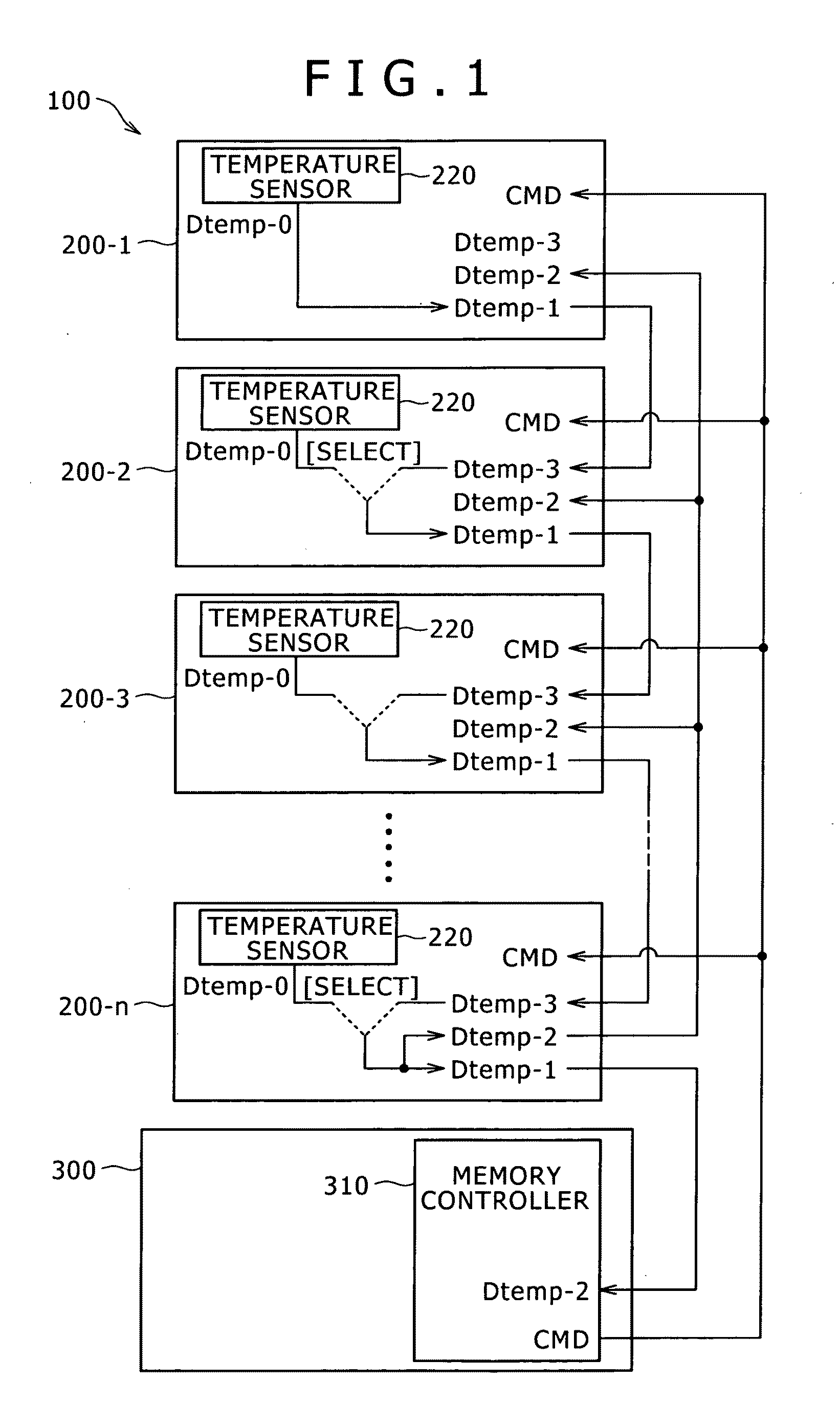
[0032]FIG. 1 illustrates an example of reception and output of temperature information in a memory system 100 according to an embodiment of the present invention that includes a plurality of memories.

[0033]The memory system 100 includes n memories, i.e., first to nth memories 200-1 to 200-n, and a logic block 300. In the present embodiment, each of the first to nth memories 200-1 to 200-n is physically formed, for example, as a discrete memory chip. Further, the logic block 300 is also formed as a chip. These chips are arranged at predetermined positions, for example, on a substrate. It should be noted that, in the description given below, the first to nth memories 200-1 to 200-n may be written as memories 200 if all or some thereof are treated collectively with no particular distinction.

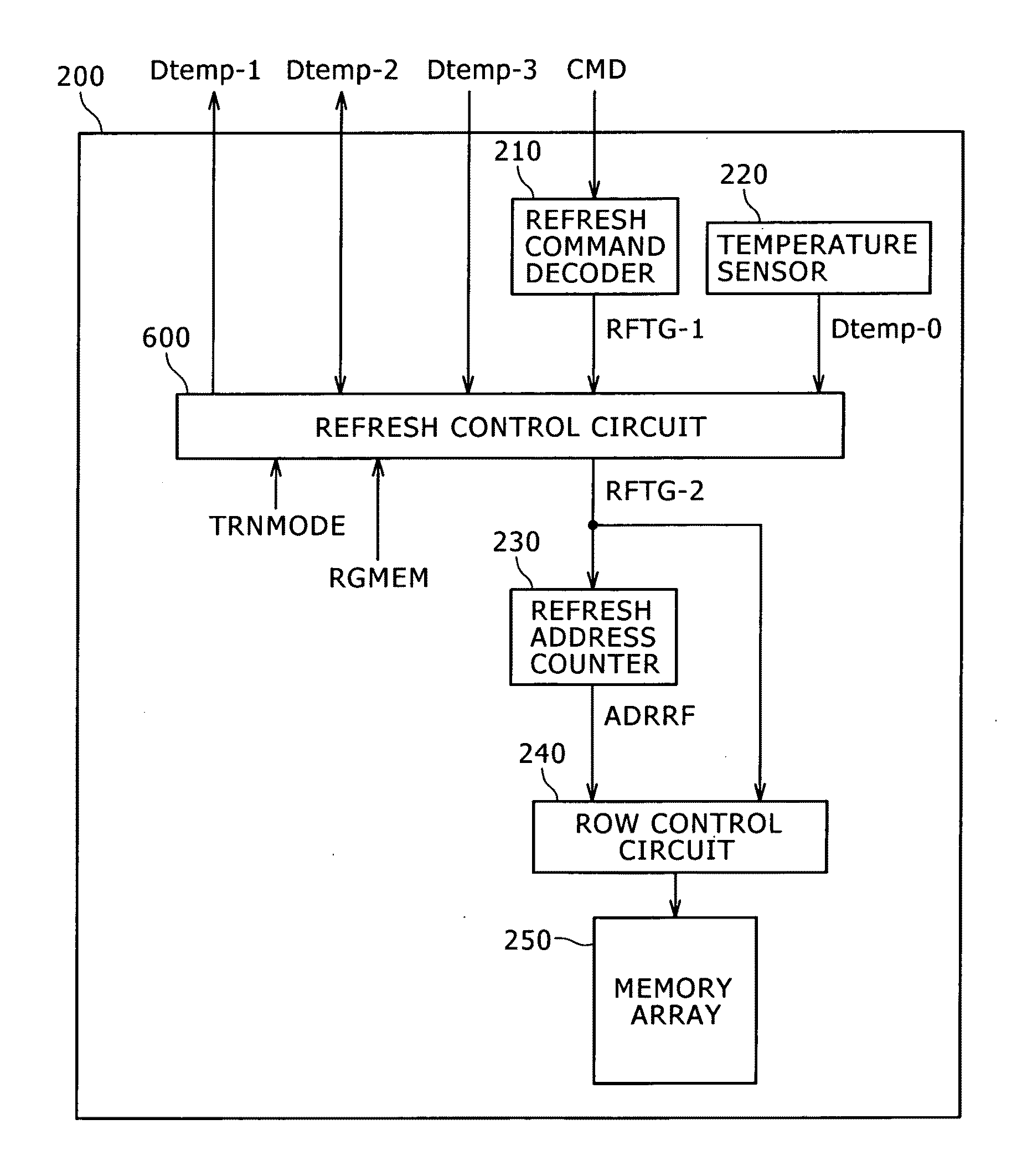
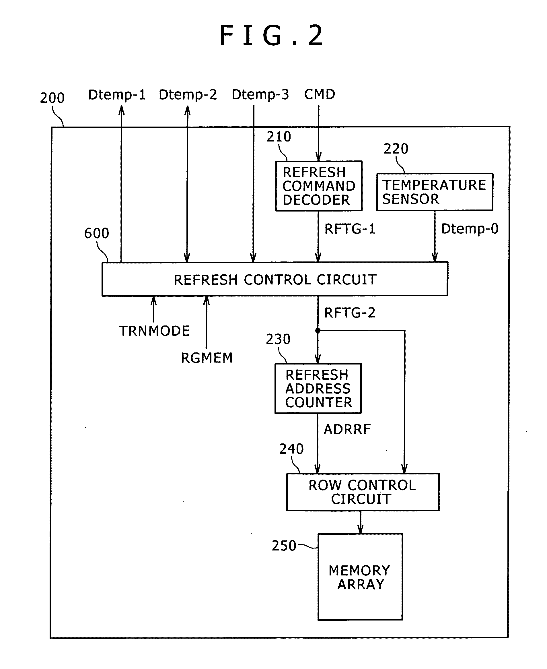
[0034]The memories 200 include, for example, a dynamic memory array and are...


PUM


Abstract

Disclosed herein is a storage control device that includes a temperature sensor, temperature information selection section, refresh command reception section and trigger issuance frequency setting section.

Description

BACKGROUND OF THE INVENTION[0001]1. Field of the Invention[0002]The present invention relates to a storage control device, storage device and storage device system and, more particularly, to a storage control device, storage device and storage device system that control refresh according to the temperature conditions of dynamic memories.[0003]2. Description of the Related Art[0004]A dynamic memory stores information by the presence or absence of an electric charge held by capacitors. This type of memory requires a refresh that is composed of reading out the data stored in the memory and rewriting the data before the charge is lost due to a leak current. On the other hand, a leak current in a dynamic memory is known to have a temperature dependence which causes the leak current to diminish at low temperatures and increase at high temperatures.[0005]Therefore, when the refresh frequency is set according to the leak current flow at high temperatures, this frequency is excessively high ...

Claims


Application Information

Patent Timeline
Patent Type & Authority Applications(United States)
IPC IPC(8): G11C11/402
CPCG11C11/406G11C11/40618G11C7/04G11C11/40626
Inventor KURODA, MASAMI
Owner SONY CORP
Why Eureka
Try Eureka