Disk drive flexure

a technology of flexure and disk drive, applied in the direction of instruments, instruments, data recording, etc., can solve the problems of affecting the electrical insulation of the conductor, deteriorating the flatness of the tongue portion or varying the thickness of the tongue section, and reducing the service life of the drive. , to achieve the effect of simplifying the wiring structur

Active Publication Date: 2012-05-31
NHK SPRING CO LTD
View PDF15 Cites 10 Cited by
  • Summary
  • Abstract
  • Description
  • Claims
  • Application Information

AI Technical Summary

Benefits of technology

[0013]Accordingly, the object of this invention is to provide a disk drive flexure provided with a slider including an attached electronic unit mounted thereon, whose wiring structure being simplified.

Problems solved by technology

Therefore, in Patent Literature 1, a wiring configuration for achieving connection of the conductors with the terminal of the slider and connection of the conductors with the terminal of the thermal assist device is complicated, and a cost required for the wiring section is increased.
Moreover, this overlap can be a factor that deteriorates flatness of the tongue portion or varies the thickness of the tongue section.
Therefore, a distance between the respective conductors is two small, and assuring electrical insulation of the conductors is difficult.

Method used


Image

  • Disk drive flexure
  • Disk drive flexure
  • Disk drive flexure

Examples


Embodiment Construction

[0034]Hereinafter, a disk drive flexure according to a first embodiment of the present invention will be described with reference to FIG. 1 to FIG. 10.

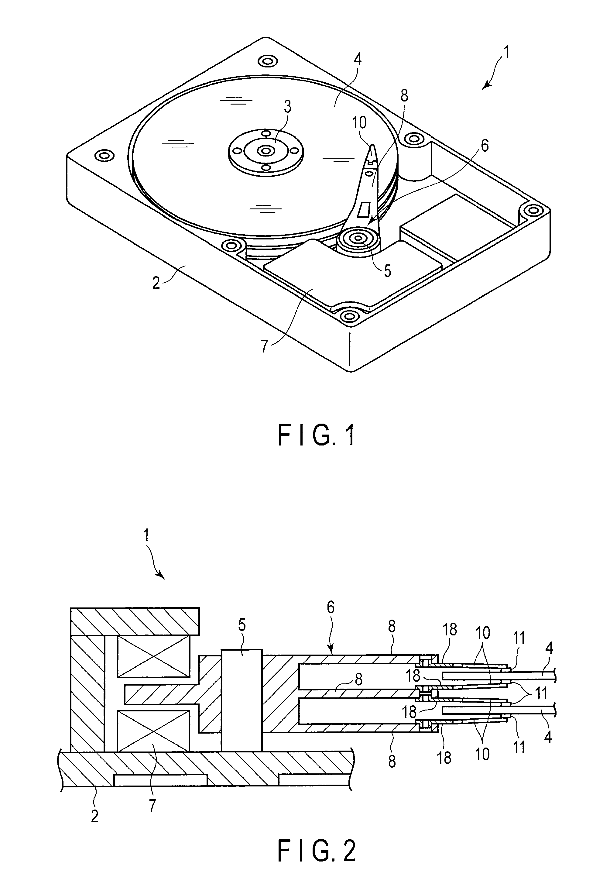
[0035]A disk drive (HDD) 1 shown in FIG. 1 has a case 2, magnetic disks 4, a carriage 6, a positioning motor 7, and others. Each disk 4 rotates about a spindle 3. The carriage 6 is turnable about a pivot 5. The positioning motor 7 drives the carriage 6. The case 2 is hermetically closed by a non-illustrated lid.

[0036]FIG. 2 is a cross-sectional view schematically showing a part of the disk drive 1. As shown in FIG. 2, arms (actuator arms) 8 are provided on the carriage 6. Suspensions 10 are disposed at distal ends of the actuator arms 8. Sliders 11 constituting magnetic heads are provided at distal ends of the suspensions 10. When each disk 4 rotates at high speed, an air bearing is formed between the disk 4 and the slider 11.

[0037]When the carriage 6 is turned by the positioning motor 7, the suspensions 10 move radially relative to t...


PUM

PropertyMeasurementUnit
thicknessaaaaaaaaaa
thicknessaaaaaaaaaa
thicknessaaaaaaaaaa

Abstract

A flexure includes a metal base and a wiring portion. The wiring portion is constituted of an insulating layer, a conductor group, and others. A tongue portion is formed to a main portion of the metal base. A slider including an attached electronic unit is disposed to the tongue portion. The conductor group includes conductors electrically connected to the slider and conductors electrically connected to the attached electronic unit. Island-shaped electrical circuit portions are formed on the metal base. The electrical circuit portions are electrically independent from the main portion of the metal base. The conductors for the attached electronic unit are electrically conductive with respect to the electrical circuit portions through conductor coupling portions piercing the insulating layer. The electrical circuit portions are connected to terminal portions of the attached electronic unit.

Description

CROSS-REFERENCE TO RELATED APPLICATIONS[0001]This application is based upon and claims the benefit of priority from prior Japanese Patent Application No. 2010-267593, filed Nov. 30, 2010, the entire contents of which are incorporated herein by reference.BACKGROUND OF THE INVENTION[0002]1. Field of the Invention[0003]The present invention relates to disk drive flexure used in a disk drive for an information processing apparatus, such as a personal computer.[0004]2. Description of the Related Art[0005]A hard disk drive (HDD) is used in an information processing apparatus such as a personal computer. The hard disk drive includes a magnetic disk rotatable about a spindle, a carriage turnable about a pivot, etc. A disk drive suspension is disposed on an arm of the carriage.[0006]The disk drive suspension has a load beam, a flexure arranged to overlap the load beam, and others. A slider is mounted on a gimbal portion formed near the distal end of the flexure. The slider is provided with e...

Claims


Application Information

Patent Timeline
Patent Type & Authority Applications(United States)
IPC IPC(8): G11B5/48
CPCG11B5/4833G11B5/4866G11B5/486
Inventor YAMADA, YUKIE
Owner NHK SPRING CO LTD
Why Eureka
Try Eureka