Data bus control method and apparatus

Inactive Publication Date: 2011-08-25
PANASONIC CORP +1
View PDF22 Cites 30 Cited by
  • Summary
  • Abstract
  • Description
  • Claims
  • Application Information

AI Technical Summary

Benefits of technology

[0009]The purpose of this invention is to provide a method to detect a hang in the I2C bus and clear the hang by resetting the affected I2C device. Un

Problems solved by technology

A problem is encountered when the I2C interface of the slave device fails to function properly in the middle of the data transfer such that the slave device pulls the serial data line 102 to logic LOW 30

Method used


Image

  • Data bus control method and apparatus
  • Data bus control method and apparatus
  • Data bus control method and apparatus

Examples


Example

Second Embodiment

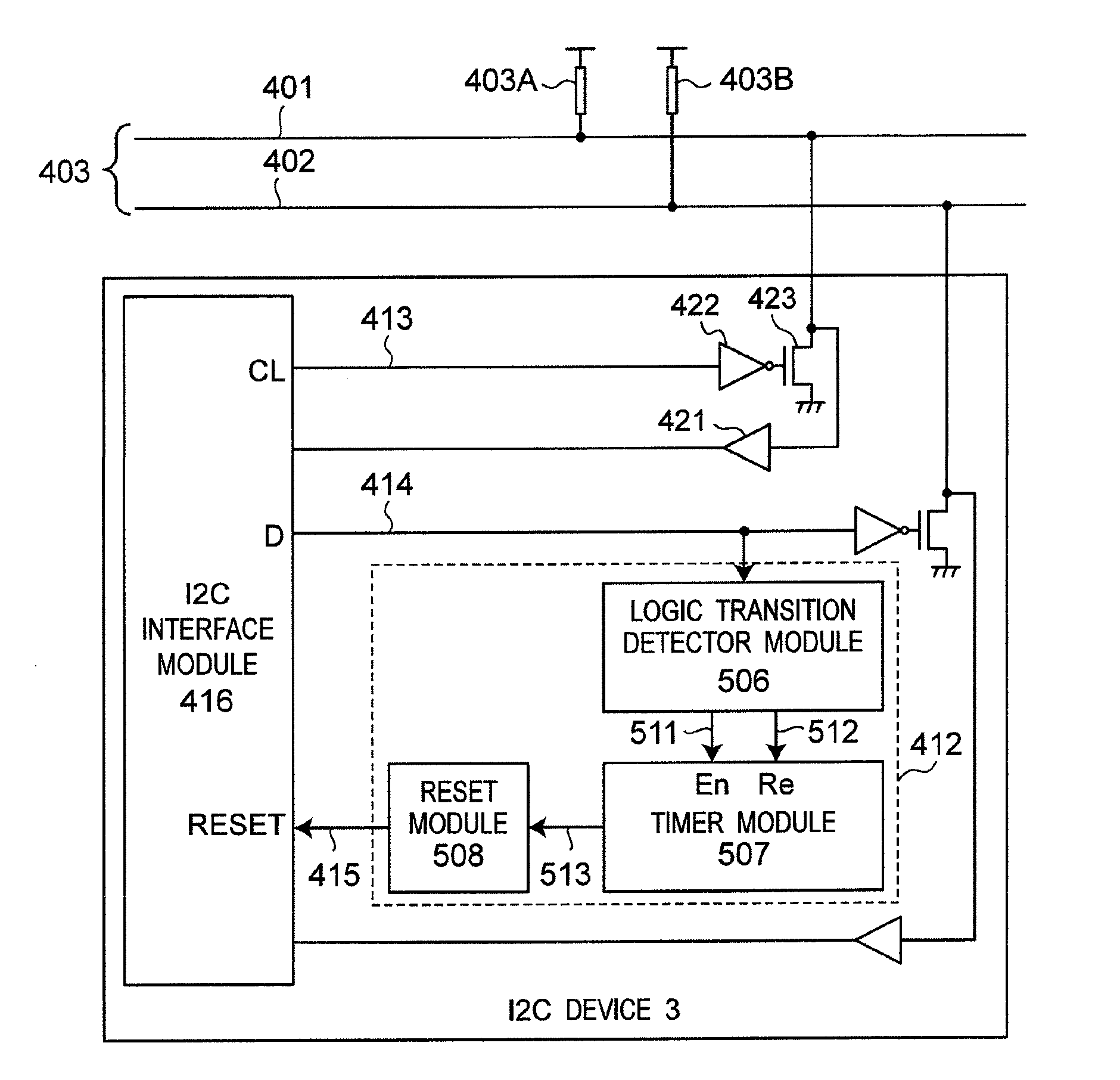
[0029]The second preferred embodiment based on the present invention, is as shown in FIG. 5A.

[0030]Referring to FIG. 5A, a schematic block diagram is showing a system for clearing a hang in the serial data line in accordance to the present invention.

[0031]In the I2C bus communication, the device which initiates a data transfer on the I2C bus 403 and generates the clock signals to permit that transfer is referred as master while any device responding to the transfer is considered a slave. In an embodiment, any of the I2C devices can act as a master or slave device. The present invention can be implemented in both master and slave. For simplicity in the drawing FIG. 5A, only one I2C device is used for explanation of the present invention.

[0032]The embodiment illustrated in FIG. 5A includes an I2C device 3 in communication over a serial clock line 401 and a serial data line 402 in an I2C system bus 403, a logic transition detector module 506, a timer module 507 and a r...

Example

Third Embodiment

[0040]The third preferred embodiment based on the present invention, is as shown in FIG. 5B.

[0041]Referring to FIG. 5B, similar to the second embodiment of FIG. 5A, for the serial clock line 401, the above operation applies, with logic transition detector module 516 coupled to the output clock line 413, and its output nodes 521 and 522 coupled to timer module 517. Timer module 517 in turn outputs the timer count to the reset module 518 via output node 523. Again, reset module 518 generates a reset pulse to the I2C interface module 416 via output node 524 when the timer count from output node 523 exceeds the predetermined time.

[0042]Referring to FIG. 6B, exemplary waveform diagrams are shown, explaining the method of operation of the third embodiment of the present invention. The description of the method refers to elements of FIG. 5B, like numbers referring to like elements.

[0043]The method starts when the logic transition detector detects a transition from logic HIG...


PUM


Abstract

A method and apparatus to prevent I2C device from hanging the I2C data bus and thus stopping other devices in the system from transmitting or receiving data is presented. A logic transition detector detects a logic transition at the output data line of an I2C device and triggers a timer. The timer starts counting after it is triggered. A reset module resets the I2C interface module in the I2C device after the timer counts to a specified period of time. The timer is reset when the logic transition detector detects another logic transition at the output data line of the I2C device.

Description

BACKGROUND OF THE INVENTION[0001]The present invention relates to a data bus control method and an apparatus thereof which are for preventing a slave device from indefinitely holding the Inter-Integrated Circuit (I2C) data bus unintentionally and thus stopping other devices in the I2C bus system from transmitting or receiving data. This condition is typically referred to as a hang condition.[0002]I2C bus is one of the most widely used communication protocol for communicating between devices in electronics systems. FIG. 1A shows a block diagram of a conventional I2C system. For simplicity, in FIG. 1A, four I2C devices are shown. However, in actual applications, there may be multiple I2C devices connected to the I2C bus 103. The I2C bus 103 requires two bi-directional bus lines, a serial clock line 101 and a serial data line 102. Collectively, both the serial clock line 101 and the serial data line 102 are referred to as I2C bus 103. Each device connected to the bus is recognized by a...

Claims


Application Information

Patent Timeline
IPC IPC(8): G06F13/00G06F1/04
CPCG06F1/04G06F13/00G06F13/4072G06F2213/0016
Inventor KWEK, ROBIN SHIH CHEANGZHANG, SHUANG
Owner PANASONIC CORP
Why Eureka
Try Eureka