
Electro-optical device, method of driving electro-optical device, and electronic apparatus

a technology of electrooptical devices and optical devices, applied in the direction of identification means, washers, instruments, etc., can solve the problems of display quality and display non-uniformity, and achieve the effect of increasing the speed of correction processing

Active Publication Date: 2005-01-13
ELEMENT CAPITAL COMMERCIAL CO PTE LTD
View PDF15 Cites 211 Cited by
  • Summary
  • Abstract
  • Description
  • Claims
  • Application Information

AI Technical Summary

Benefits of technology

[0007] It is another object of the invention to increase the speed of the correction processing.

Problems solved by technology

However, there are various disturbance factors, other than the above-mentioned temperature factor, that affect the display quality, for example, ambient luminance during the use of the electro-optical device, the deterioration over time of the electro-optical elements included in the pixels, and non-uniformity of display due to differences in the manufacturing of the display panels.

Method used


Image

  • Electro-optical device, method of driving electro-optical device, and electronic apparatus
  • Electro-optical device, method of driving electro-optical device, and electronic apparatus
  • Electro-optical device, method of driving electro-optical device, and electronic apparatus

Examples


second embodiment

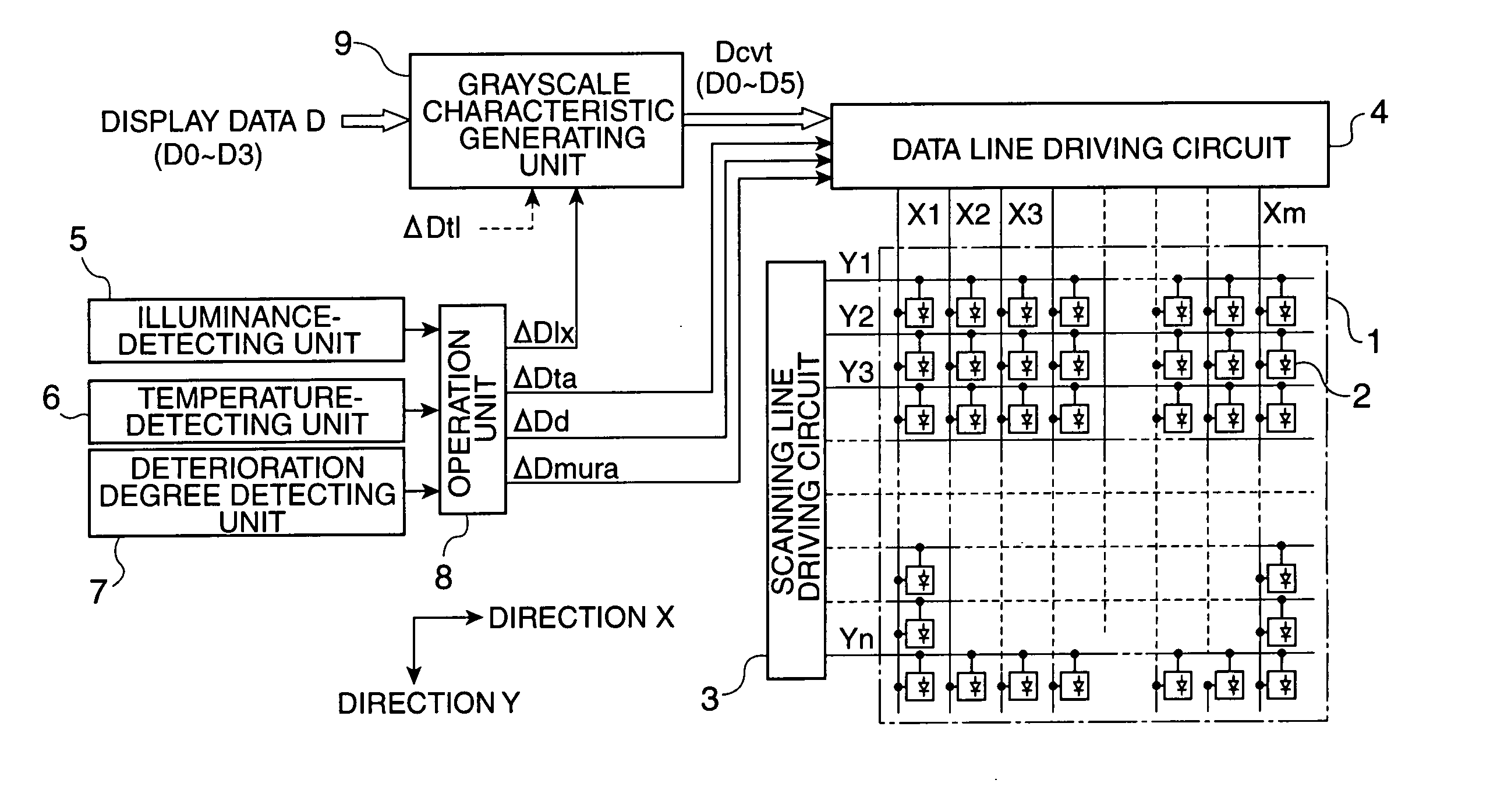
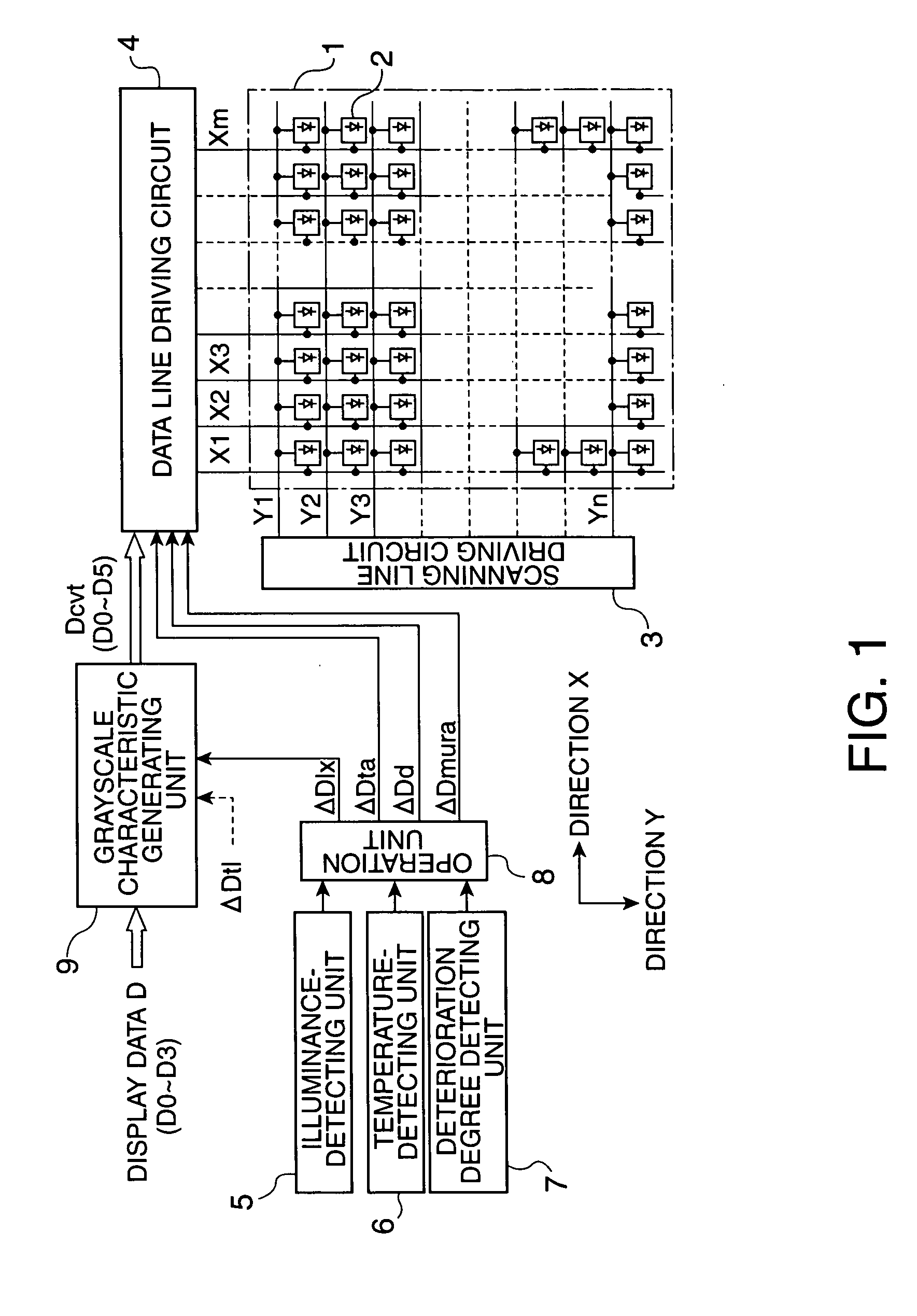
[0096]FIG. 18 is an exemplary block diagram of the current DAC 46 according to the The current DAC 46 includes a data signal generating unit 46a for generating the data signal supplied to the pixel 2 on the basis of a current as a main body, the correction value generating unit 46b, and the driving voltage correcting unit 46d, in addition to the data signal generating unit 46a. The structure of FIG. 18 is different from that of FIG. 14 in the structure of the data signal generating unit 46a and in that the driving voltage correcting unit 46d is provided instead of the grayscale correcting unit 46c. Since the structure of the circuit elements of FIG. 18 is the same as that of the circuit elements of FIG. 14, excluding the above-mentioned differences, the circuit elements of FIG. 18 will be denoted by the same reference numerals as those of FIG. 14, and description thereof will be omitted.

[0097] The data signal generating unit 46a can be provided between the data lines X and the refe...

third embodiment

[0101]FIG. 20 is a view illustrating the schematic characteristics of a In the embodiment, correction in which the two correction factors ΔD1x and ΔDt1 are taken into account is performed by the LUT processing of the grayscale characteristic generating unit 9 to thus generate conversion data Dcvt from the display data D. The data signal generating unit 46a that constitutes a part of the pixel-driving unit directly generates the data current Idata from the conversion data Dcvt without considering the three correction factors ΔDd, ΔDmura, and ΔDta and supplies the data current Idata to the pixels 2 through the data lines X.

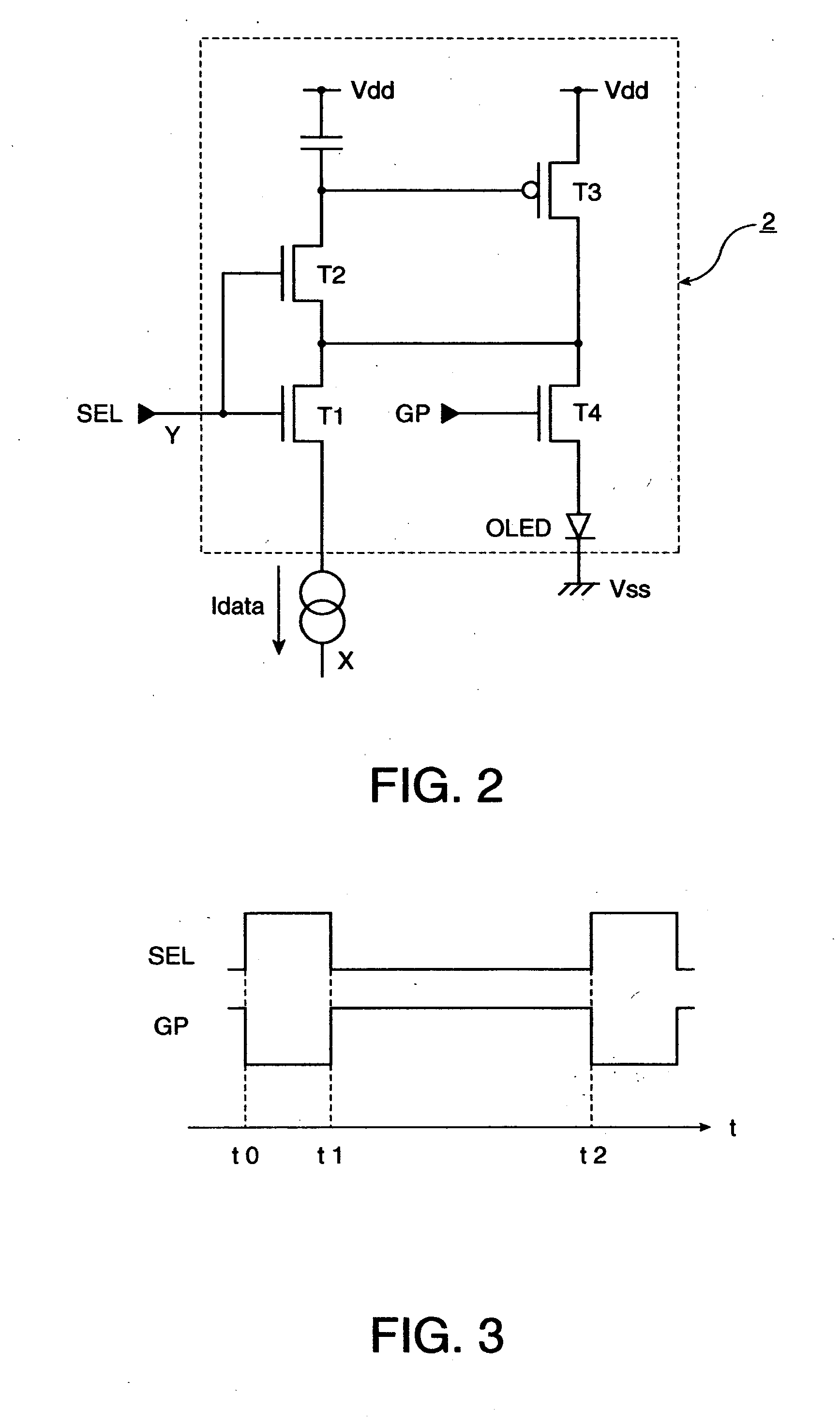
[0102] On the other hand, a driving period controlling unit 10 that constitutes a part of the pixel-driving unit controls the driving period of the pixel 2 illustrated in FIG. 2 after considering the three correction factors ΔDd, ΔDmura, and ΔDta. FIG. 21 is a driving timing chart of the pixel 2, as an example. Delay time At is set between the falling timing t1 of ...


PUM


Abstract

The invention provides an electro-optical device that stabilizes display quality by performing correction processing corresponding to a plurality of disturbance factors. Specifically, a grayscale characteristic generating unit can generate conversion data having grayscale characteristics obtained by changing the grayscale characteristics of display data that defines the grayscales of pixels with reference to a conversion table whose description contents include correction factors. A data line driving circuit can drive the pixels after correcting the grayscale characteristics of the conversion data by the correction factors using other processing different from the that performed by the grayscale characteristic generating unit.

Description

BACKGROUND OF THE INVENTION [0001] 1. Field of Invention [0002] The present invention relates to an electro-optical device, a method of driving the electro-optical device, and an electronic apparatus, and more particularly, to processing of correcting display data for defining grayscales of a pixel. [0003] 2. Description of Related Art [0004] Conventionally, electro-optical devices having a correcting function in order to suppress the deterioration of display quality due to disturbance factors are known. For example, a technology for detecting changes in temperature accompanied by heat generation of organic EL elements by a plurality of temperature sensors provided in a display panel and correcting the driving of the display panel in accordance with the detected change is disclosed in Japanese Unexamined Patent Application Publication No. 2002-175046. SUMMARY OF THE INVENTION [0005] However, there are various disturbance factors, other than the above-mentioned temperature factor, th...

Claims


Application Information

Patent Timeline
IPC IPC(8): H01L51/50G09F9/00G09G3/20G09G3/30G09G3/32H04N5/70
CPCG09G3/20G09G3/2014G09G3/2018G09G3/325G09G3/3275G09G2300/0842G09G2360/144G09G2320/0276G09G2320/0285G09G2320/041G09G2320/048G09G2320/0626G09G2340/0428G09G2300/0861F16B39/24F16B43/00
Inventor KASAI, TOSHIYUKIIMAMURA, YOICHI
Owner ELEMENT CAPITAL COMMERCIAL CO PTE LTD
Learn More