Device for suspending a sliding door

a technology for sliding doors and devices, applied in mechanical equipment, wing accessories, manufacturing tools, etc., can solve the problems of noisy door running, roller wedges, plastic support rollers,

Inactive Publication Date: 2011-09-01
KNORR BREMSE GMBH
View PDF13 Cites 6 Cited by
  • Summary
  • Abstract
  • Description
  • Claims
  • Application Information

AI Technical Summary

Benefits of technology

Disclosed embodiments address these issues in the conventional technology and provide a door guide which does not have the above-mentioned problems. According to the disclosed embodiments, a steel insert having at least a substantially circular track is embedded in the supporting rail, in that the supporting rollers are designed as steel rollers having a concave cross-sectional shape on the running surface, and in that an adjustment roller is provided, the adjustment roller bearing under pre-stress against the adjustment surface of the supporting rail, the adjustment surface lying opposite the steel insert.

Problems solved by technology

Another problem in all of the previously known door guides is that the supporting rail is an aluminum section, and in that the supporting rollers consist of plastic.
This does not appear to be a problem at first sight, but even high-quality plastics have a tendency to absorb water and, in the process, change their geometrical dimensions, and therefore, depending on the operating conditions (summer-winter, day-night, sunny side-shade side, etc.), there is a repeated tendency either for the rollers to become wedged and to be damaged by overcoming the wedge, or for the seat, which is geometrically as accurate as possible but is never actually free from play, to become too loose, which may result in noisy running of the door and in turn, due to the impacts caused during the noisy running, to differing types of damage.

Method used


Image

  • Device for suspending a sliding door
  • Device for suspending a sliding door
  • Device for suspending a sliding door

Examples


Embodiment Construction

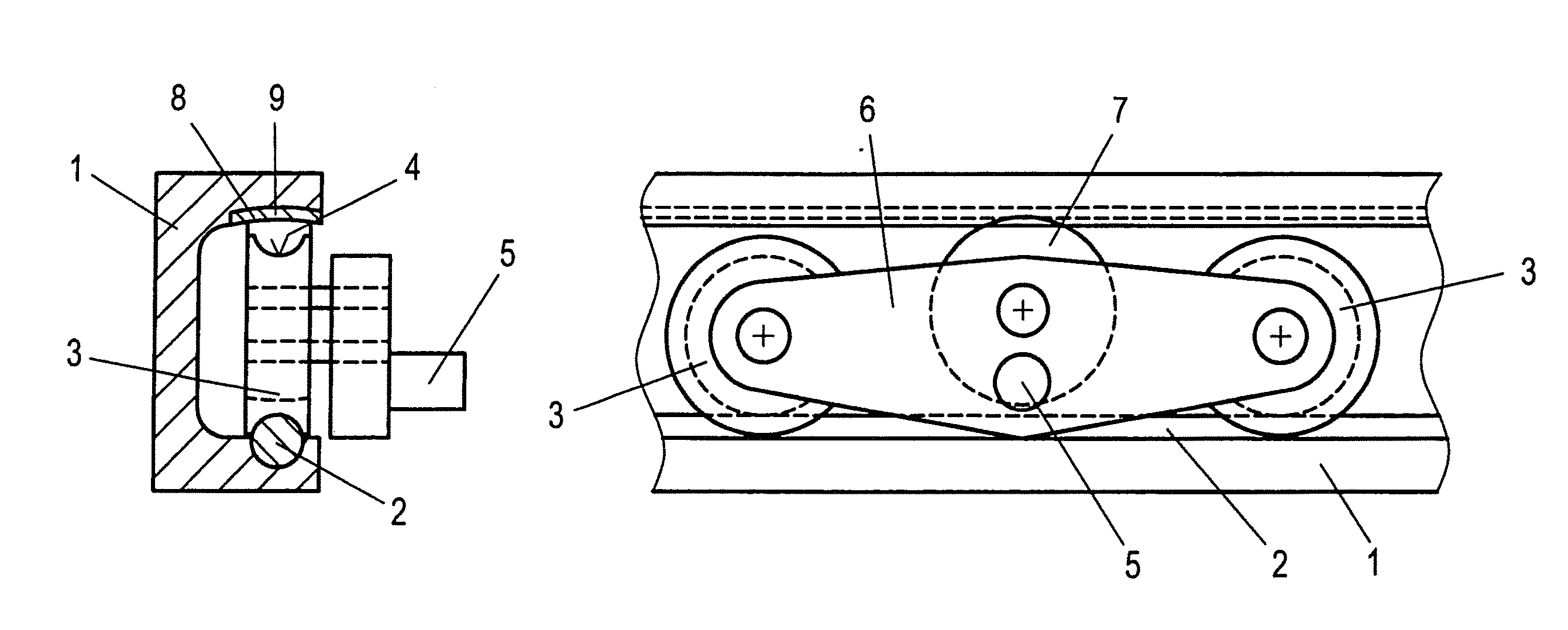
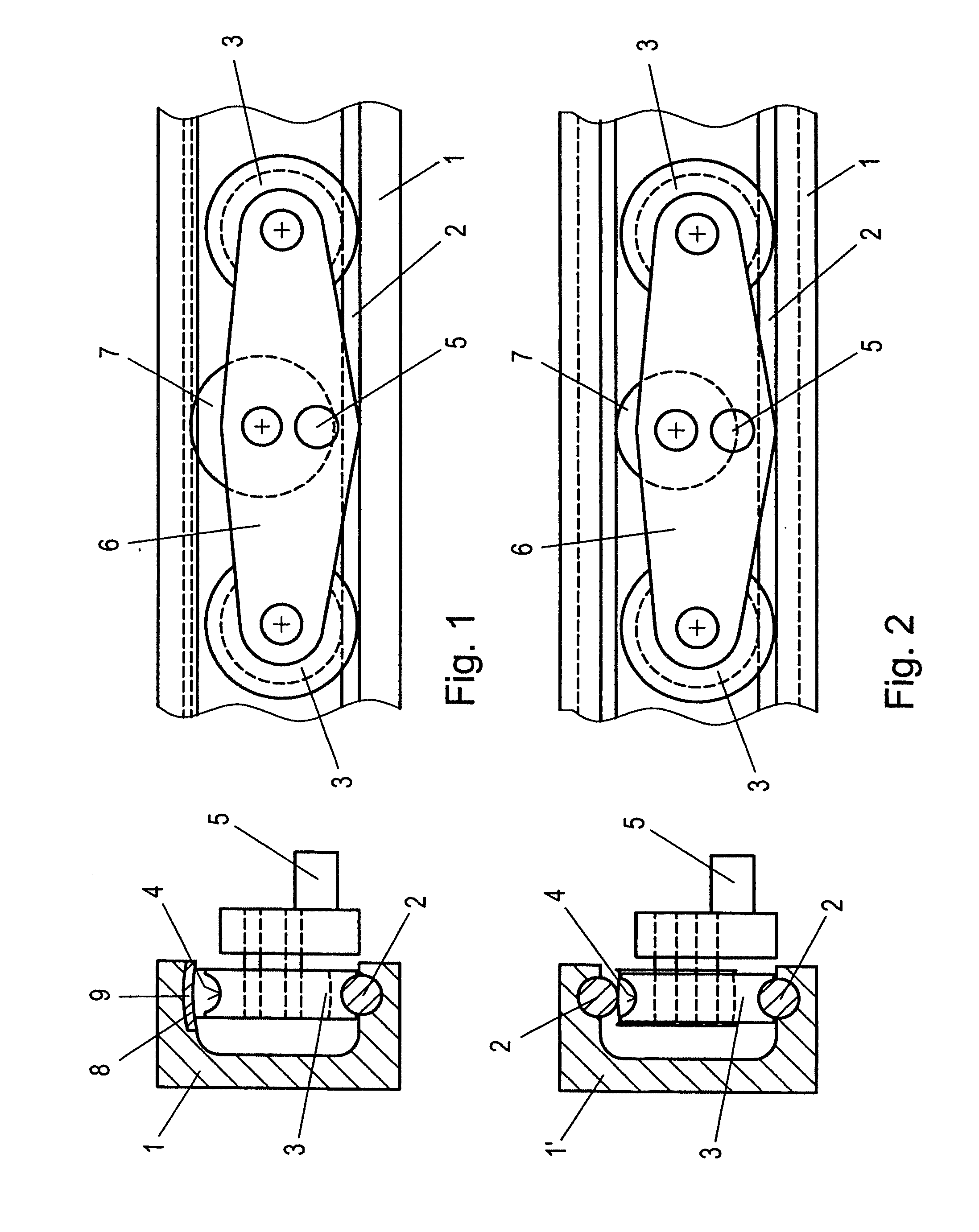
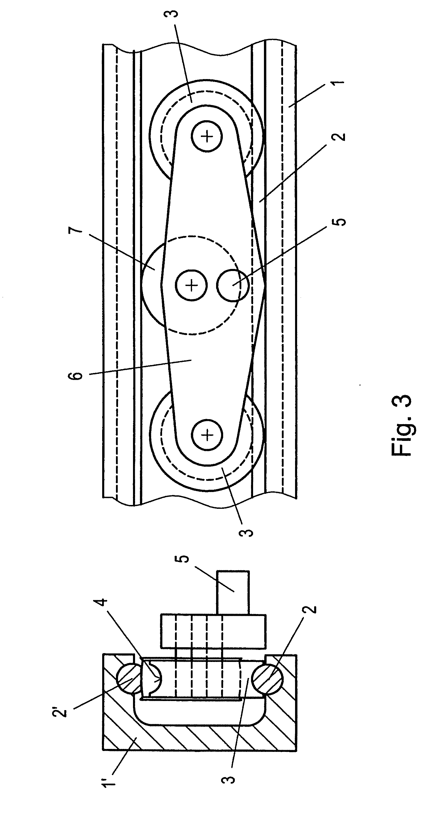
In accordance with the disclosed embodiments two supporting rollers and one tensioning roller may be provided per fastening point of the door leaf to the supporting rail. The effect achieved by this measure is an extremely accurate guide, in which the steel insert in the supporting rail creates the possibility of also producing the supporting roller from steel and of thus maintaining the geometrical dimensions with a high degree of accuracy. The adjustment roller can either consist of plastic, in which case the pre-stressing may be achieved by elastic deformation of the adjustment roller, or the adjustment roller may also be a steel roller, with the mounting then potentially being spring-loaded.

FIG. 1 shows a door guide according to the invention in a schematic side view and in section normally to the supporting rail. The door guide has a supporting rail 1 which generally has a C-shaped cross section. The lower region of the supporting rail 1 has a steel insert 2 which is circular i...


PUM


Abstract

The invention relates to the suspension of a door leaf of a sliding door in rail-bound, mass transportation vehicles, such as underground railways, passenger train cars, means of local public transportation, and the like. The suspension mechanism includes carrying rollers in a carrying rail arranged in the upper region of the door leaf or above the door leaf. The invention includes a steel insert having an at least substantially circular track inserted into the carrying rail; the carrying rollers are designed as steel rollers having a concave cross-sectional shape on the running surface, and an adjustment roller is provided, which abuts the adjustment surface of the carrying rail opposite of the steel insert under preload.

Description

FIELD OF THE INVENTIONDisclosed embodiments relate to a means of suspending a door leaf of a sliding door in rail-bound means of mass transportation, such as subways, passenger train cars, means of local public transportation, etc., by means of supporting rollers in a supporting rail arranged in the upper region of the door leaf or above the door leaf.BACKGROUNDDoor suspending means of this type should be designed to be as free from play as possible in order to guarantee quiet running of the door. At the same time, however, the entire door suspending means comprising the supporting rail which runs in the upper door region or above the door and is mounted on the car body, and rollers which are connected to the door leaf and run on the supporting rail, for which purpose use is also made of guides which act at least in the lower region of the door leaf, should permit a certain degree of mobility, in particular rotatability about the axis of the supporting rail, in order to be able to c...

Claims


Application Information

Patent Timeline
Patent Type & Authority Applications(United States)
IPC IPC(8): E05D15/06E05F15/56
CPCE05D15/0626E05D15/0652E05Y2900/132E05Y2201/614E05Y2201/684Y10T16/364E05Y2800/21E05Y2900/51E05F15/565E05F15/655E05Y2201/688F16C29/12
Inventor PRITZ, CHRISTIANJETZINGER, PETER
Owner KNORR BREMSE GMBH
Why Eureka
Try Eureka