Image forming apparatus

a technology of forming apparatus and forming tube, which is applied in the direction of electrographic process apparatus, instruments, optics, etc., can solve the problems of inability to take effective measures for the problem, the problem of fine particles different from ozone or toner powder dust, and the apparatus has come to be seen as a problem,

Active Publication Date: 2011-09-01
KONICA MINOLTA BUSINESS TECH INC
View PDF28 Cites 51 Cited by
  • Summary
  • Abstract
  • Description
  • Claims
  • Application Information

AI Technical Summary

Problems solved by technology

However, with a recent increase in awareness of global environmental conservation, fine particles which are substances different from ozone or toner powder dust, particularly ultra fine particles (with a particle size of 100 nm or less) generated from electrophotographic image forming apparatuses have come to be seen as a problem.
Up to now, it has been unknown where in the inside of an image forming apparatus the ultra fine particles are generated, and therefore it has been impossible to take effective measures for the problem.
Further, if an exhaust fan, which is for sucking air of the fixing device containing the ultra fine particles, is constantly used at a maximum rotation frequency, the fixing device is cooled, which results in deteriorated fixability and increased energy consumption.

Method used


Image

  • Image forming apparatus
  • Image forming apparatus
  • Image forming apparatus

Examples


first embodiment

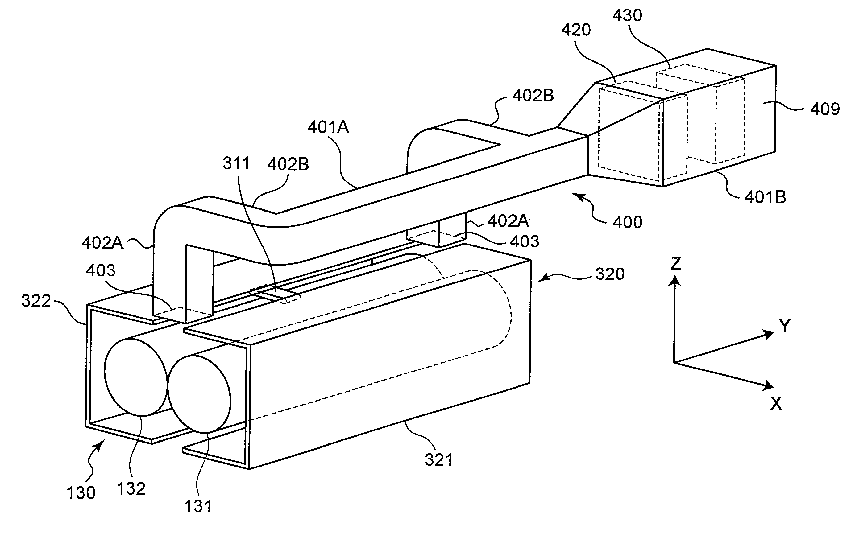
[0048]FIG. 4A shows a cross sectional configuration of the internal expanded section 401B and the vicinity thereof in the image forming apparatus 100. The filter member 420 is fixedly provided in the expanded section 401B. The size of the cross section of the first filter member 420 is equal to the size of the cross section of the expanded section 401B at a position where the first filter member 420 is provided. Consequently, in the state shown in FIG. 4A, an air flow A1 generated by the exhaust fan 430 all passes through the filter member 420. On the other hand, in the state shown in FIG. 4B, an air flow A2 generated by the exhaust fan 430 also all passes through the first filter member 420 as in FIG. 4A.

[0049]FIG. 7A shows a flow chart for control of the exhaust fan 430 by the control section 200 of the image forming apparatus 100. Table 1 shows control of the exhaust fan 430 by the control section 200 in every generation state of the ultra fine particles.

TABLE 1State(a)(b)(c)Ultr...

second embodiment

[0060]FIG. 5A shows a cross sectional configuration of inside the internal expanded section 401B, exhaust fans in one aspect (denoted by reference signs 431, 432) and the vicinity thereof in the image forming apparatus 100. It is to be noted that in the second embodiment, component members identical to those in the first embodiment are designated by identical reference signs to omit explanation.

[0061]As shown in FIG. 5A, the expanded section 401B has a first path 411 and a second path 412 parallel to the first path 411 formed by a divider plate 413. A filter member 421 is fixedly provided in the expanded section 401B upstream from the first path 411 and the second path 412 so as to close the expanded section 401B. The size of the cross section of the filter member 421 is equal to the size of the cross section of the expanded section 401B at a position where the filter member 421 is provided. The first exhaust fan 431 is provided in the first path 411. The second exhaust fan 432 is p...

third embodiment

[0068]FIG. 6A shows a cross sectional configuration inside the internal expanded section 401B, exhaust fans in one aspect (denoted by reference signs 431, 432) and the vicinity thereof in the image forming apparatus 100. It is to be noted that in the third embodiment, component members identical to those in the second embodiment are designated by identical reference signs to omit explanation.

[0069]As shown in FIG. 6A, the filter member 422 is fixedly provided in a second path 412 upstream from the second exhaust fan 432 so as to infill the second path 412. The size of the cross section of the filter member 422 is equal to the size of the cross section of the second path 412 at a position where the filter member 422 is provided. Consequently, in the state shown in FIG. 6A, i.e., in the state when only the first exhaust fan 431 rotates, an air flow A5 all travels through a first path 411. In the state shown in FIG. 6A, i.e., in the state where only the second exhaust fan 432 rotates, ...


PUM


Abstract

An image forming apparatus includes a fixing member having a cylindrical or annular shape for fixing an image onto a sheet which is in pressure contact with an outer surface thereof; and a heating source for heating the fixing member to a fixing temperature. A duct is provided in a position facing the fixing member with respect to a width direction perpendicular to a circumferential direction of the fixing member and which has an inlet for taking in fine particles generated from the fixing member. A filter member is provided inside the duct and which can trap the fine particles which flow through the duct. An exhaust fan is provided in the duct upstream or downstream from the filter member for generating an air flow going from the inlet to an outlet of the duct. A control section controls the operation of the exhaust fan according to initial burst conditions under which the fine particles are emitted from the fixing member.

Description

[0001]This application is based on an application No. 2010-42150 filed in Japan on Feb. 26, 2010, the entire content of which is hereby incorporated by reference.BACKGROUND ART[0002]The present invention relates to an image forming apparatus, more particularly to an electrophotographic image forming apparatus such as printers, copying machines and facsimile machines.[0003]It is known for this kind of an electrophotographic image forming apparatus that several kinds of chemical substances are emitted during imaging operation. Typical chemical substances to be emitted (chemical emission) include ozone generated during charging of a photoconductor and toner powder dust generated during developing or fixing operation. Conventional solutions to the chemical emission include taking measures against the emission source of such chemicals emission so as to decline the emission amount itself, and providing a filter to prevent emitted substances from being discharged to the outside of the appa...

Claims


Application Information

Patent Timeline
Patent Type & Authority Applications(United States)
IPC IPC(8): G03G21/00G03G21/20
CPCG03G15/2064G03G2221/1645G03G21/206
Inventor SHIMOYAMA, ATSUHIKOYOSHIKAWA, SHOICHITASHIRO, SHIGERUOOMOTO, NOBORUTOSO, YOSHIYUKIMATSUNAGA, TOU
Owner KONICA MINOLTA BUSINESS TECH INC
Why Eureka
Try Eureka