Clamping mechanism for shear testing apparatus

a technology of shear testing and clamping mechanism, which is applied in the direction of instruments, measurement devices, scientific instruments, etc., can solve the problems of difficult difficulty in sensing contact with the substrate surface, and inconvenient us

Active Publication Date: 2011-09-08
NORDSON CORP
View PDF7 Cites 13 Cited by
  • Summary
  • Abstract
  • Description
  • Claims
  • Application Information

AI Technical Summary

Benefits of technology

[0018]a baseplate, the shear test tool attached the baseplate by a resilient connector that allows for movement of the shear test tool relative to the baseplate in an axial direction which is perpendicular to the test direction;

Problems solved by technology

Several difficulties arise.
Friction and stiction in the mechanism of the device itself may cause difficulties in sensing contact with the substrate surface.
Imprecise surface sensing will inevitably affect the distance by which the test tool is withdrawn, and thus the height at which the bond is sheared.
Such movement may seriously affect the accuracy of the test results and significant movement of the test tool at the test height may damage an adjacent bond or wire.
The twin objectives of both a low contact force when sensing the surface of the substrate and accurate control of the test height are difficult to resolve.
However, they still suffer from some disadvantages.
A first disadvantage is the relatively high cost of these systems.
The air-bearing is a relatively expensive component in the overall cost of a shear testing tool.
A second disadvantage is that during a test procedure much of the load has to be supported by the cantilever arms.
This means that for tests at higher loads, larger, and consequently more massive, cantilever arms must be used.
This in turn leads to a larger touchdown force when initially positioning the sensor, which can lead to damage to the substrate surface.
This has also resulted in different cantilever arm assemblies being used for different load tests, further increasing cost.
A third disadvantage is that in both the air-bearing solution and the compressed air activated piston solution, the test head is moved laterally as the cantilever arms are urged or pressed against the baseplate, so that it can be positioned relative to the substrate but prior to the test being performed.
The switching off of the air-bearing or the clamping of the test tool against the baseplate inevitably means some vertical movement will occur in addition to the lateral movement of the test head.
This movement can reduce the accuracy of the resulting test, especially given the extremely small step off distance involved.

Method used


Image

  • Clamping mechanism for shear testing apparatus
  • Clamping mechanism for shear testing apparatus
  • Clamping mechanism for shear testing apparatus

Examples


Embodiment Construction

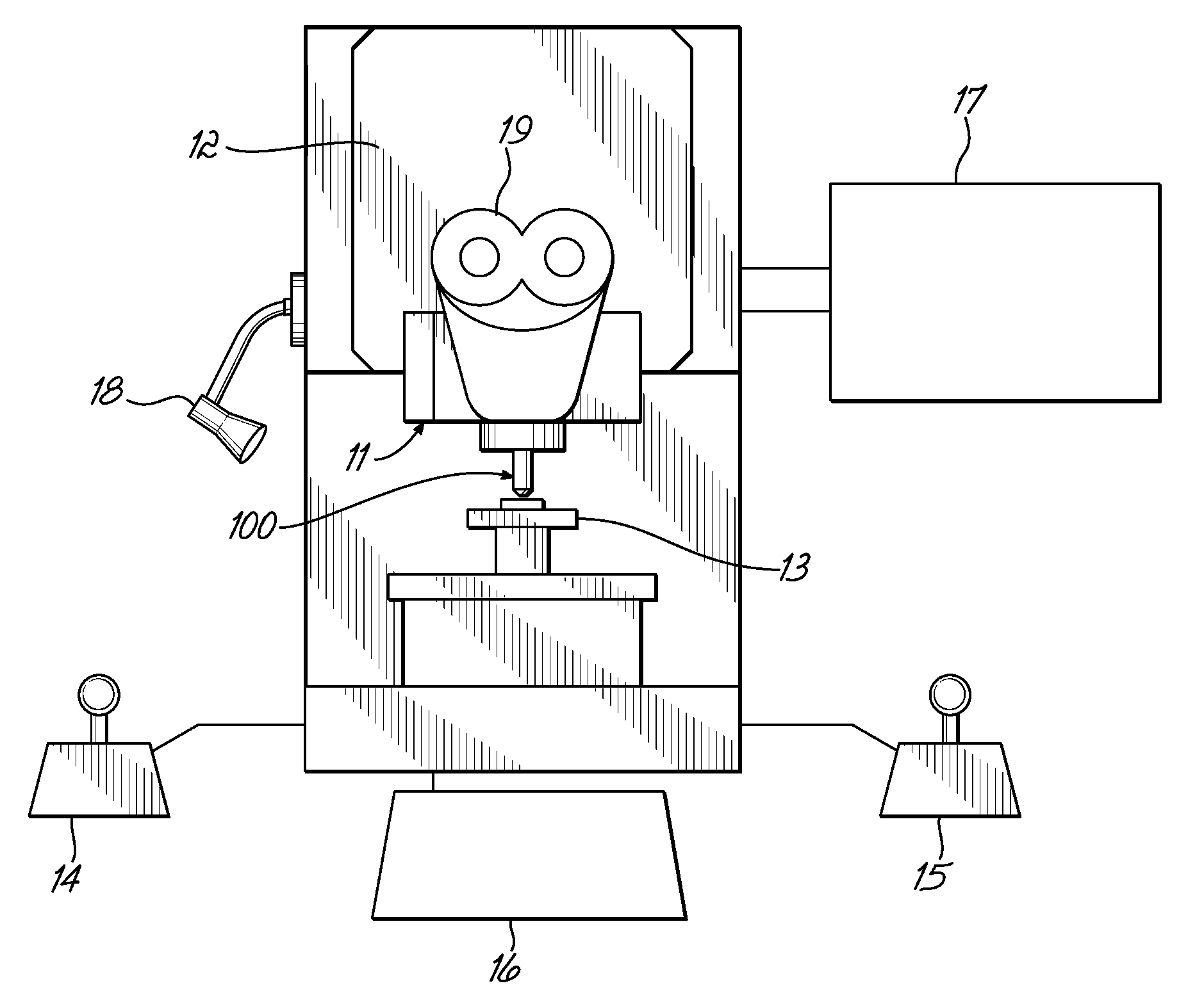
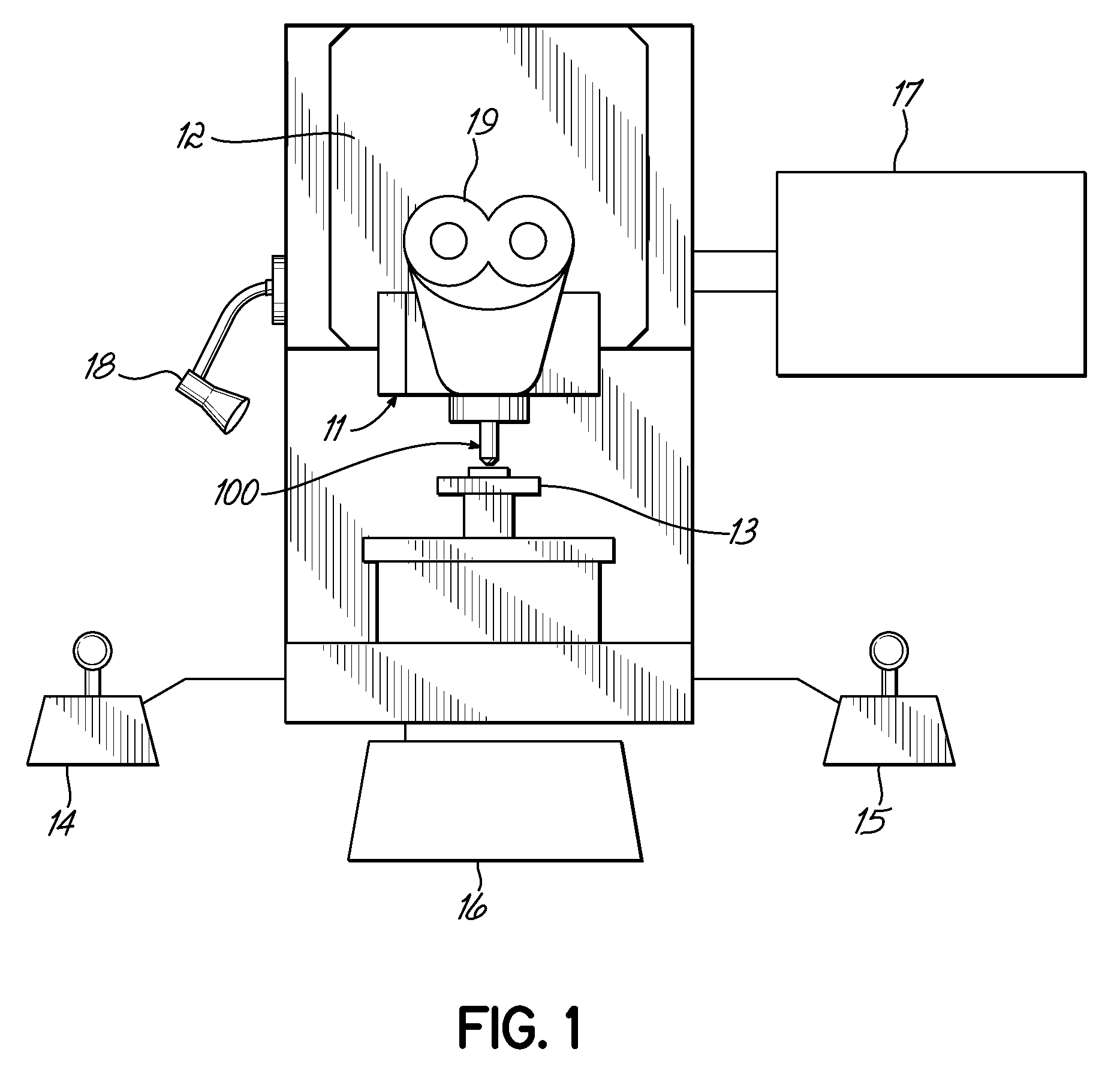
[0045]FIG. 1 is an illustration of a shear testing device 12 in accordance with the present invention. The device 12 comprises a shear test tool 100 mounted to a cartridge 11, which is itself mounted to the main body of the device 12. Beneath the shear test tool 100 is a motorised stage table 13, on which samples to be tested can be mounted. As shown in FIG. 3, the samples are typically substrates 300 upon which solder ball deposits 302 are formed that are connected to electronic circuitry (not shown) within the substrate 300.

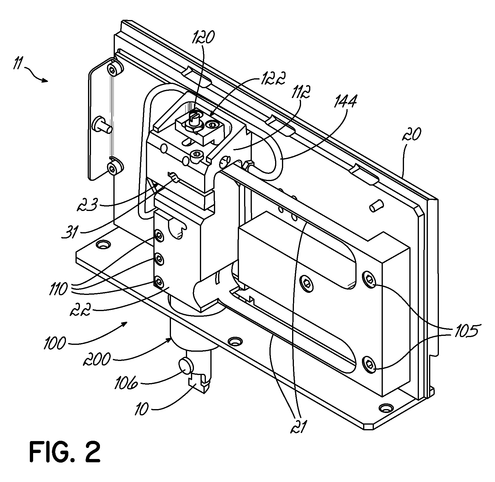
[0046]As best shown in FIG. 3, the shear test tool 100 includes a shear test head 10 that is secured in a tool holder 200, which is in turn security in a shear body 22. As will later be described in more detail, the test head 10 applies a shear force to the ball deposits 302 on a substrate 300 under test. The shear test tool 100 includes strain gauges (later described) for measuring the shear force experienced by the test head 10 as the ball deposit 302 is shea...


PUM

PropertyMeasurementUnit
strengthaaaaaaaaaa
clamping forceaaaaaaaaaa
bond strengthaaaaaaaaaa

Abstract

A shear test device for testing the strength of attachment between a bond and an electronic substrate. The device incorporates a clamping mechanism and a shear test tool that are mounted on a baseplate. During a set-up procedure, the shear test tool is movable relative to the baseplate. During a test procedure, the shear test tool is clamped by the clamping mechanism in a fixed position relative to the baseplate. At least one abutment is provided that is fixed in position relative to the baseplate. During the test procedure, a drive mechanism provides relative movement between the shear test tool and the bond to cause the shear test tool to shear the bond off the substrate. The at least one abutment provides an additional clamping force on the test tool while the test tool is shearing the bond off of the substrate. Strain gauges associated with the shear test tool provide signals to an electric circuit indicating the strength of attachment between the bond and the substrate.

Description

FIELD OF THE INVENTION[0001]The present invention relates to shear testing tools. In particular, the invention relates to a device and method that allows movement of a shear testing tool relative to a mounting plate during a set-up procedure but maintains the shear testing tool in a fixed position relative to the mounting plate during a shear test procedure.BACKGROUND TO THE INVENTION[0002]Semiconductor devices are very small, typically from 5 mm square to 50 mm square, and typically comprise numerous sites for the bonding of electrical conductors to the semiconductor substrate. Each bond consists of a solder or gold ball deposit adhered to the substrate. It is necessary to test the strength of the attachment between the bond and the substrate, known as the bond strength, in order to be confident that the bonding method is adequate and that the bond strength is sufficient. Because of the very small size of the bonds, tools used to test the bond strength must be both very accurately ...

Claims


Application Information

Patent Timeline
Patent Type & Authority Applications(United States)
IPC IPC(8): G01N3/24
CPCG01N3/24G01N2203/0025G01N19/04
Inventor LILLEY, DAVIDBUGG, MARTINSYKES, ROBERT JOHN
Owner NORDSON CORP
Why Eureka
Try Eureka