Magnetic separation apparatus and waste water treatment apparatus

Inactive Publication Date: 2011-09-08
HITACHI LTD
View PDF5 Cites 7 Cited by
  • Summary
  • Abstract
  • Description
  • Claims
  • Application Information

AI Technical Summary

Benefits of technology

[0033]As described above, the magnetic separation apparatus and the waste water treatment apparatus can efficiently collect a

Problems solved by technology

Disadvantages of conventional magnetic separation apparatuses occur because there is a portion in which a

Method used


Image

  • Magnetic separation apparatus and waste water treatment apparatus
  • Magnetic separation apparatus and waste water treatment apparatus
  • Magnetic separation apparatus and waste water treatment apparatus

Examples


first embodiment

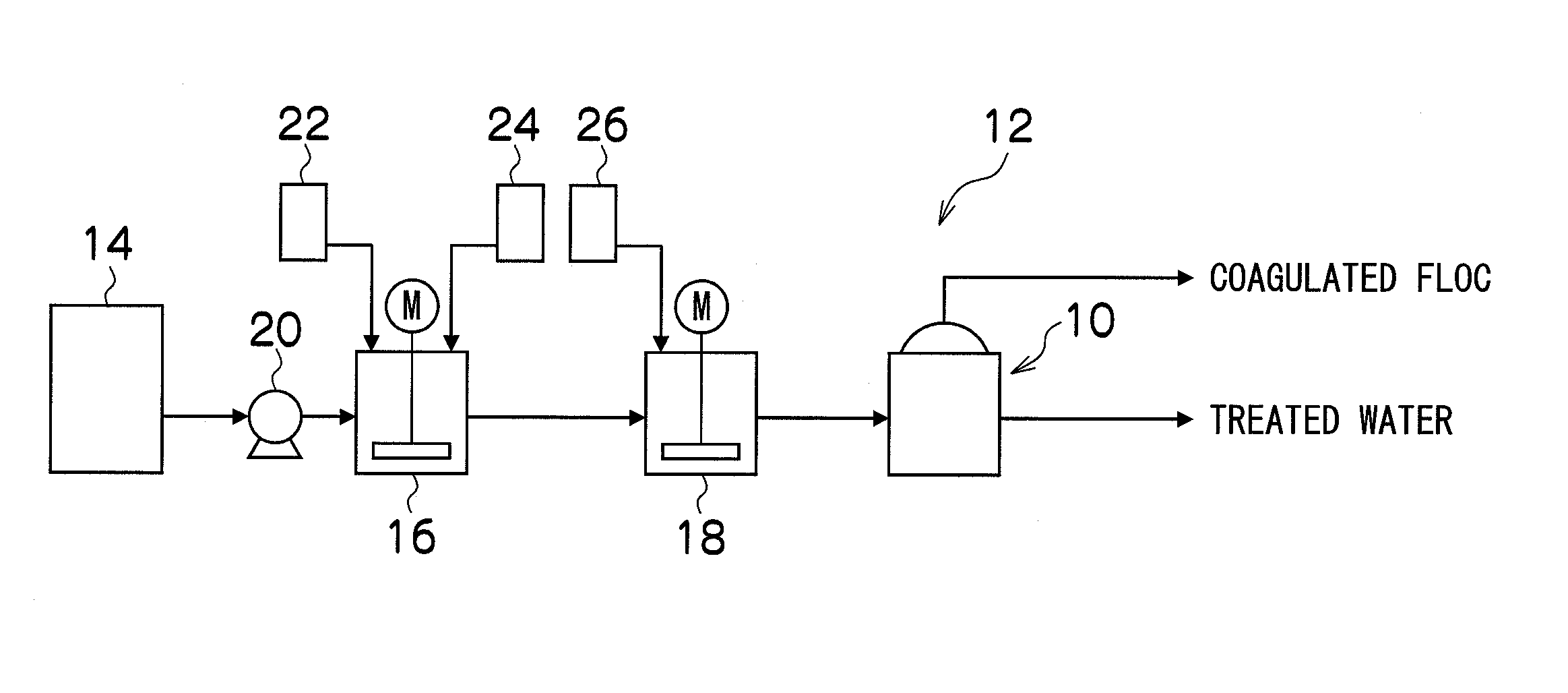
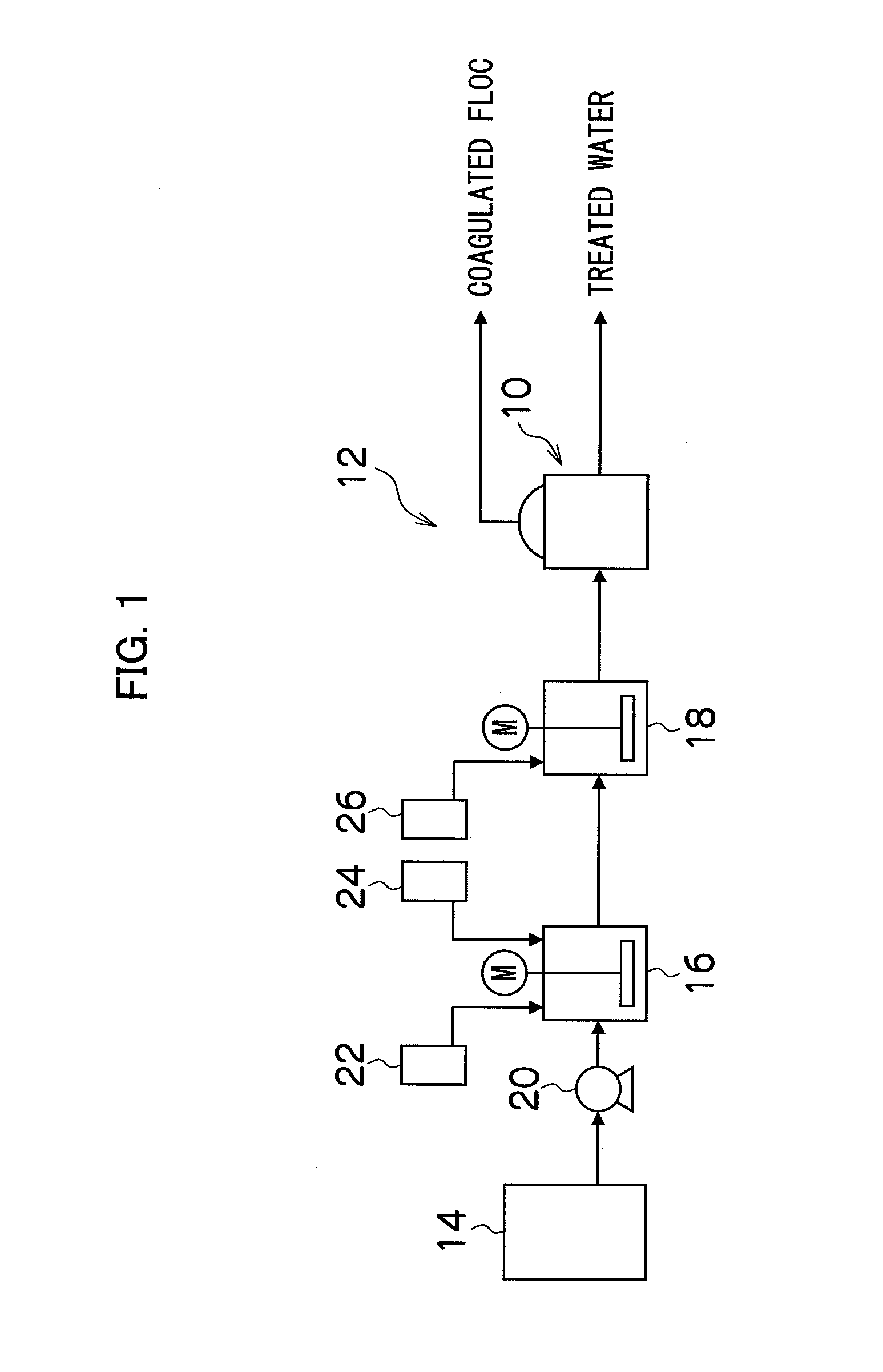
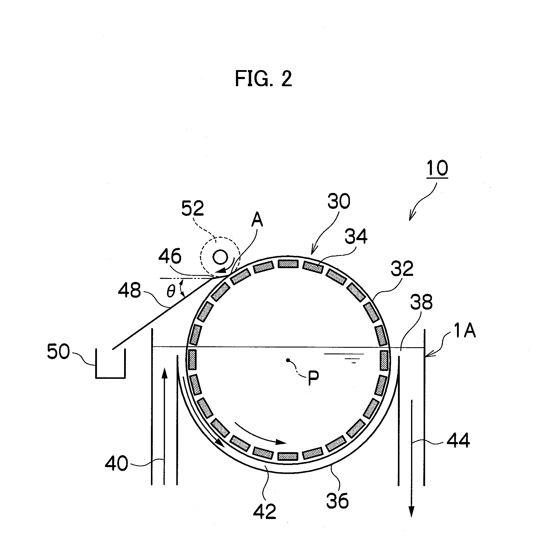
[0046]FIG. 2 is a side sectional view of the magnetic separation apparatus 10 of a

[0047]The magnetic separation apparatus 10 includes a drum separator 30.

[0048]The separator 30 includes a drum rotor 32, and a group of magnets 34 constituted by multiple magnets placed along an inner peripheral surface of the drum rotor 32, and has a structure in which the drum rotor 32 and the group of magnets 34 can be integrally rotated around a center P. The separator 30 is placed in a separation vessel 36 having a semicircular section so that a lower half thereof is submerged in waste water 38. The drum rotor 32 may be made of metal or resin. Specifically, the drum rotor 32 may be made of a material that can apply a magnetic force of the group of magnets 34 to the magnetic floc.

[0049]The group of magnets 34 have a structure in which, for example, multiple neodymium magnets are attached, and are placed so that adjacent magnets have different polarity directions to increase a magnetic gradient near...

second embodiment

[0061]FIG. 3 is a side sectional view of a magnetic separation apparatus 10A of a

third embodiment

[0062]FIG. 4 is a side sectional view of a magnetic separation apparatus 10B of a


PUM

PropertyMeasurementUnit
Flow rateaaaaaaaaaa
Heightaaaaaaaaaa
Velocityaaaaaaaaaa

Abstract

A magnetic separation apparatus comprising:
    • a separation vessel into which waste water containing a coagulated magnetic floc is supplied;
    • a drum separator that is provided in the separation vessel and adsorbs the magnetic floc with a magnetic force while being rotated;
    • a scraper that is abutted against a surface of the separator and scrapes the magnetic floc adsorbed by the surface of the separator;
    • a scraper guide that is connected to the scraper and discharges the magnetic floc scraped by the scraper; and
    • a scraping brush that scrapes the magnetic floc scraped by the scraper from the scraper and guides the magnetic floc to the scraper guide,
    • wherein a lower portion of the separator is submerged in the waste water in the separation vessel, a rotational direction of the separation vessel in the waste water is set to the same direction as a flow direction of the waste water flowing in the separation vessel, and
    • a rotational direction of the scraping brush is set to a direction opposite to the rotational direction of the separator.

Description

BACKGROUND OF THE INVENTION[0001]1. Field of the Invention[0002]The present invention relates to a magnetic separation apparatus and a waste water treatment apparatus, and more particularly to a magnetic separation apparatus and a waste water treatment apparatus that separates suspended solid, oil, or heavy metal from waste water containing suspended solid, oil, or heavy metal and obtains treated water.[0003]2. Description of the Related Art[0004]As an apparatus that separates suspended solid, oil, or heavy metal from waste water containing suspended solid, oil, or heavy metal, a waste water treatment apparatus using a magnetic separation apparatus has been conventionally known. The waste water treatment apparatus adds magnetic powder to waste water when coagulating and treating suspended solid, oil, or heavy metal contained in waste water, separates a coagulated floc (hereinafter referred to as a magnetic floc) containing magnetic powder with a magnetic force of the magnetic separa...

Claims


Application Information

Patent Timeline
IPC IPC(8): C02F1/48C02F1/52
CPCC02F1/52C02F1/48C02F1/488C02F1/5245C02F11/126C02F2101/20C02F2101/32C02F2303/14
Inventor ISOGAMI, HISASHIMIYABAYASHI, SATOSHIMORITA, MINORU
Owner HITACHI LTD
Why Eureka
Try Eureka