Video projector

Inactive Publication Date: 2011-09-08
SANYO ELECTRIC CO LTD
View PDF8 Cites 25 Cited by
  • Summary
  • Abstract
  • Description
  • Claims
  • Application Information

AI Technical Summary

Benefits of technology

[0007]The cooling structures of the prior art may be effective when the video projector is in the upright projection state or the suspended projection state. However, these structures are not effective when the vid

Problems solved by technology

However, these structures are not effective when the video projector is arranged in an upwardly directed projection state, in which it projects images in an upward direction, or a downwardly d

Method used


Image

  • Video projector
  • Video projector
  • Video projector

Examples


Embodiment Construction

[0031]A video projector according to one embodiment of the present invention will now be discussed with reference to the drawings.

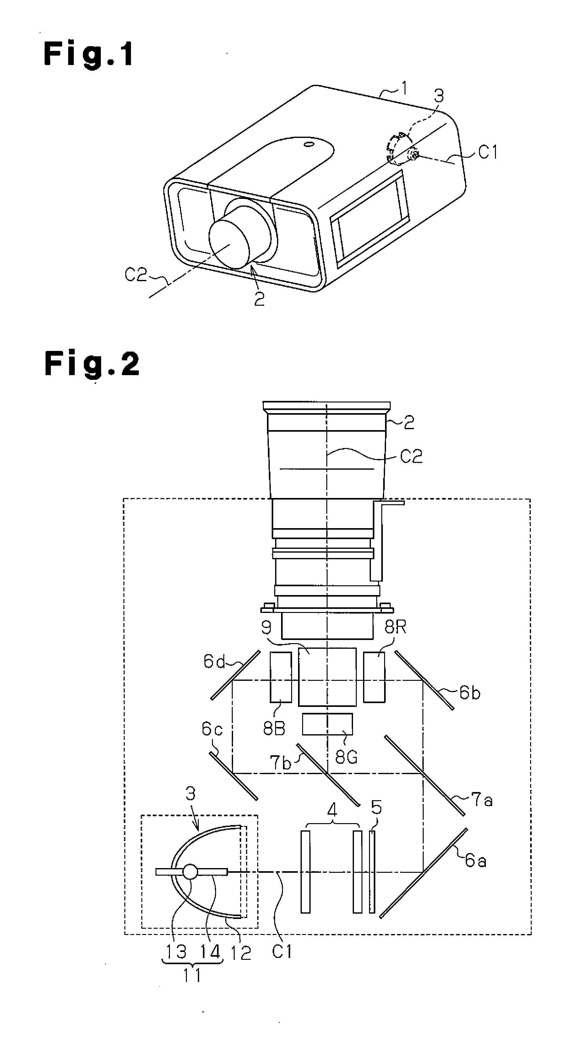
[0032]Referring to FIG. 1, the video projector of the embodiment is a three-chip LCD projector including a housing 1 and a projection lens 2, which is arranged on the front surface of the housing 1. FIG. 1 is a perspective view taken from a diagonally upward position showing the video projector in an upright projection state. In the description hereafter, unless otherwise specified, the direction of gravity will be used as a frame of reference that defines the upward and downward directions. Thus, the upper and lower sides of the projector as viewed in FIG. 1 would be reversed when the projector is suspended from a ceiling. Further, the frontward direction of the projector refers to the direction in which light travels.

[0033]The video projector includes an optical system, which will now be described with reference to FIG. 2. The optical system includes op...


PUM


Abstract

A video projector including a lamp cooling system that cools a light source lamp. The lamp cooling system includes an airflow deflection unit that varies the direction in which cooling air flows when a projection direction of the video projector changes. The airflow deflection unit uses gravitational force to automatically change the direction in which cooling air flows so that the cooling air is concentrated at an upper portion of the arc tube regardless of the changed video projector.

Description

CROSS-REFERENCE TO RELATED APPLICATIONS[0001]This application is based upon and claims the benefit of priority from prior Japanese Patent Application No. 2010-048100, filed on Mar. 4, 2010, the entire contents of which are incorporated herein by reference.BACKGROUND ART[0002]The present invention relates to a video projector that uses air to cool a light source lamp.[0003]A video projector includes a light source lamp such as a metal halide lamp. A light source lamp includes an arc tube. As viewed in the direction gravitational force acts, that is, in the vertical direction, the arc tube of the light source includes an upper portion and a lower portion. The temperature of the upper portion becomes higher than that of the lower portion. The temperature of the overall arc tube in the light source lamp must be kept within an optimal range to increase the performance of the light source lamp to the highest level and prolong the life of the light source lamp.[0004]The video projector may...

Claims


Application Information

Patent Timeline
IPC IPC(8): G03B21/16
CPCG03B21/16G03B21/145G03B21/2066
Inventor KITAMURA, SATOSHINODA, SHINYA
Owner SANYO ELECTRIC CO LTD
Why Eureka
Try Eureka