Inflation and monitoring assembly for a pressure cuff of an endotracheal tube

Active Publication Date: 2011-09-15
SEEDLINGS LIFE SCI VENTURES
View PDF32 Cites 11 Cited by
  • Summary
  • Abstract
  • Description
  • Claims
  • Application Information

AI Technical Summary

Benefits of technology

[0013]Other operative and structural features include a window disposed on the casing to facilitate the visual observation of at least a portion of the indicator member. As a result, personnel may easily and efficiently monitor the pressure within the cuff by visually determining the position of the indicator member within the casing. Moreover, the portion of the indicator member viewable through the window may include informative alpha/numeric indicia, color coding, etc. which provides the observer with a clear and easily determinable visual indication as to an acceptable or non-acceptable pressure level within the retaining cuff. In addition, in order to further facilitate the visual observation of the pressure reading, the window may incorporate a magnifying lens or similar structure to make viewing easier. Yet additional embodiments of the present invention may include an LED or other appropriate digital readout, as well as an audible and/or visual warning in the event of an over inflation condition of the cuff

Problems solved by technology

As a result, once the casing of the assembly is disconnected from the inflating lumen,

Method used


Image

  • Inflation and monitoring assembly for a pressure cuff of an endotracheal tube
  • Inflation and monitoring assembly for a pressure cuff of an endotracheal tube
  • Inflation and monitoring assembly for a pressure cuff of an endotracheal tube

Examples


Example

[0033]Like reference numerals refer to like parts throughout the several views of the drawings.

DETAILED DESCRIPTION OF THE PREFERRED EMBODIMENT

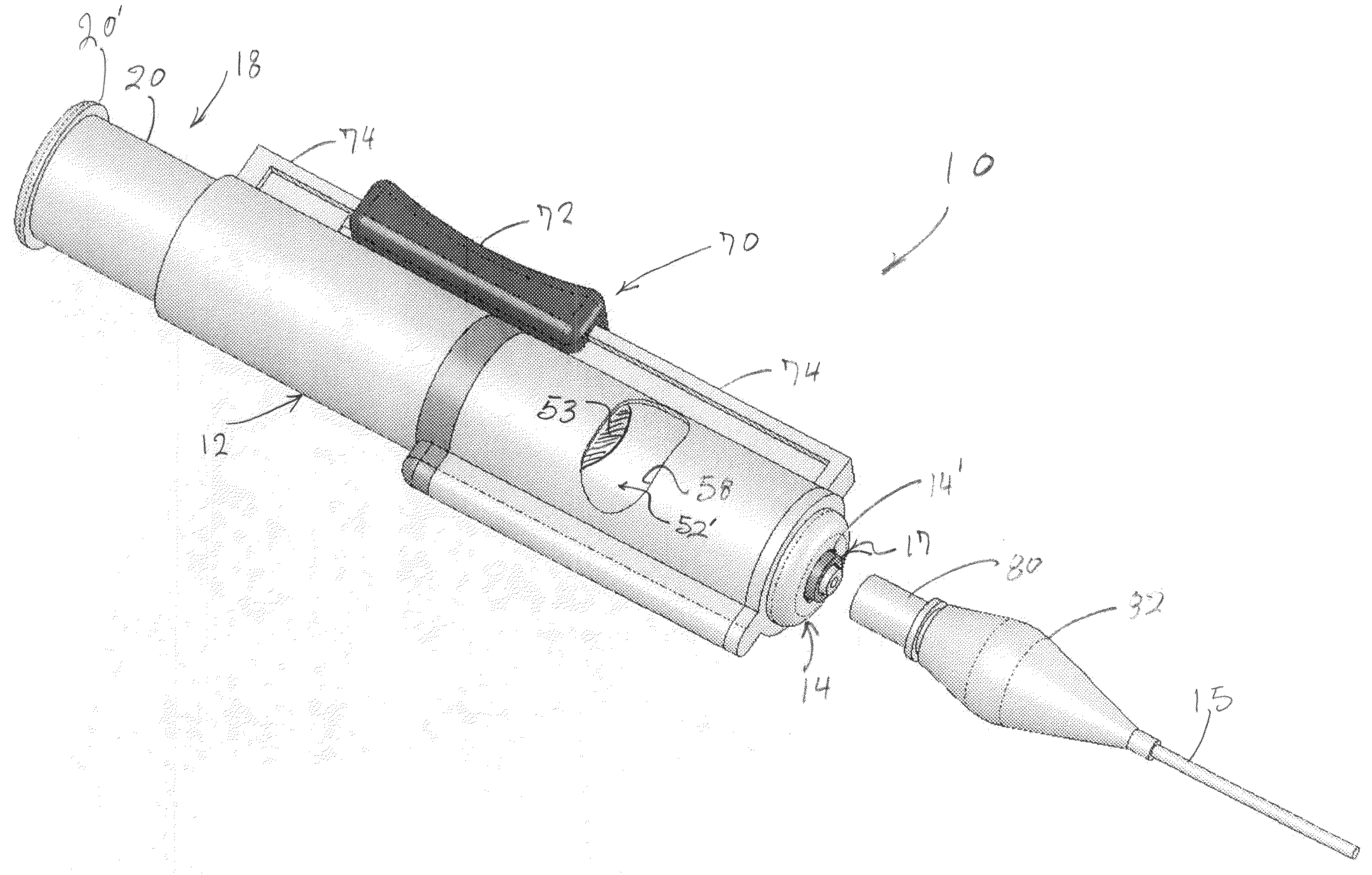
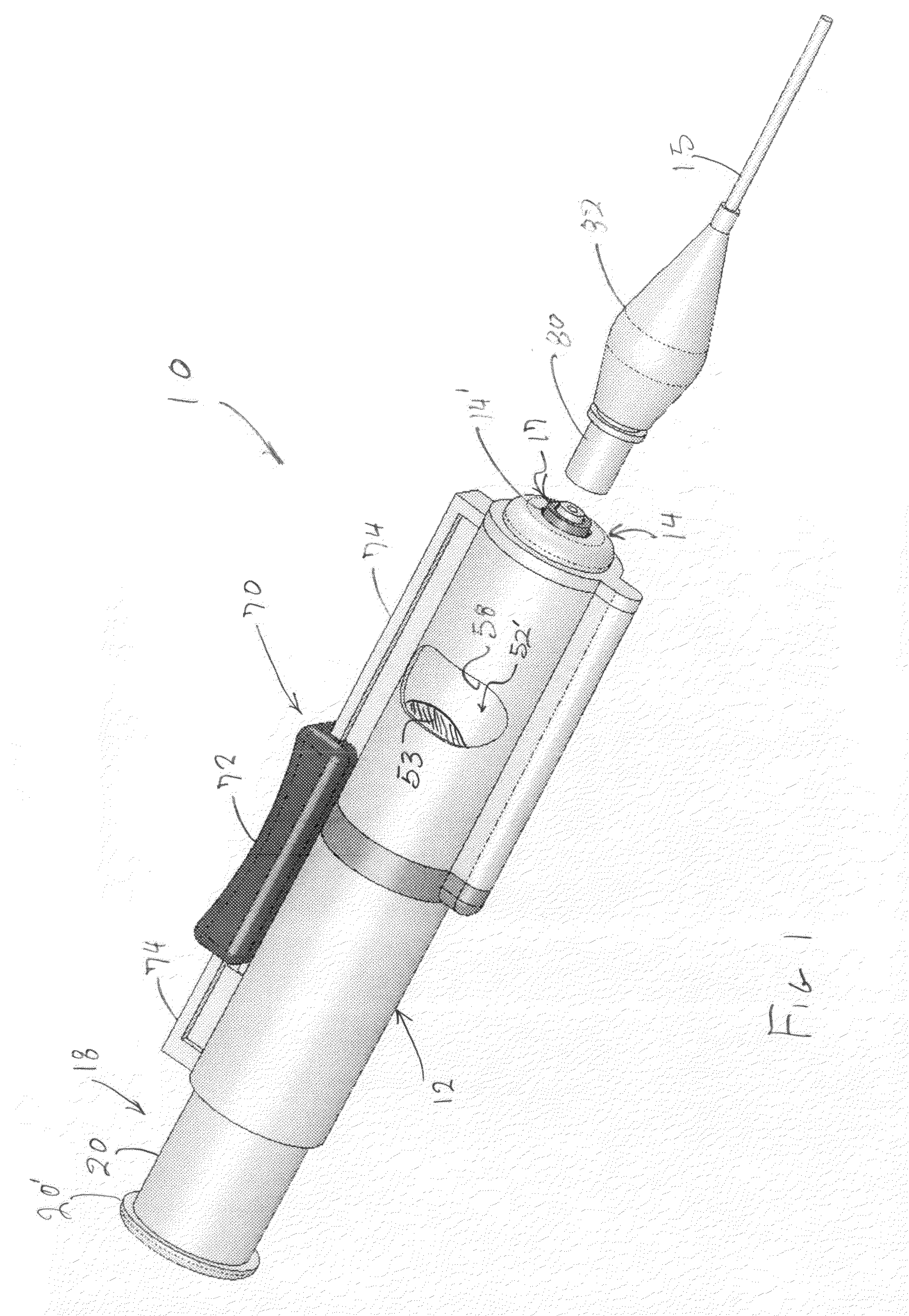
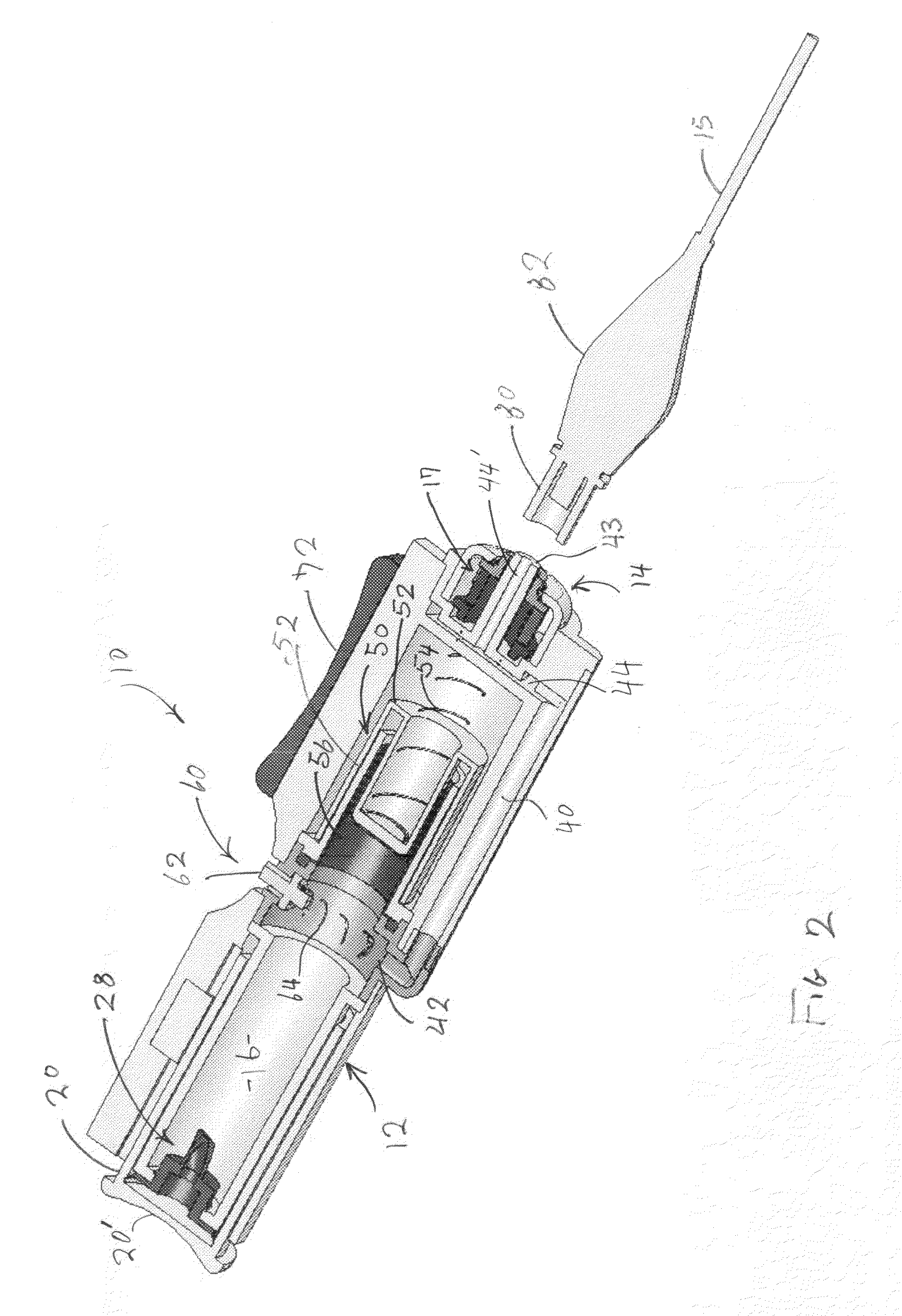
[0034]As shown in the accompanying drawings, the present invention is directed to an inflation and pressure monitoring assembly generally indicated as 10. The assembly 10 structured to inflate and monitor the pressure within a retaining cuff or pressure cuff of the type associated with an endotracheal tube.

[0035]More specifically, the assembly 10 includes a generally elongated casing 12 having a distal end generally indicated as 14 structured to be interconnected to an inflation lumen 15, which will be described in greater detail hereinafter, by means of a connection assembly 17. The connection assembly 17 is accessible through a receiving port 14′ associated with the proximal end 14 of the casing 12, and will be described hereinafter with primary reference to FIGS. 12 through 17. As such, the assembly 10 is intended to be interconnected in f...


PUM


Abstract

An assembly structured to inflate a retaining or pressure cuff of the type associated with an artificial airway tube such as an endotracheal tube and/or tracheostomy tube and concurrently monitor pressure therein including a casing having a pressure chamber on its interior. A pump assembly is movably connected to the casing and structured to force fluid flow to the retaining cuff, for inflation, through said pressure chamber. An indicator member is disposed within the casing and is visually accessible through casing window, wherein the indicator member is variably positionable dependent on and indicative of existing pressure within the retaining cuff. The existing pressure within the pressure chamber is substantially equivalent to that within the retaining cuff thereby facilitating the variable position of the indicator member to be indicative of pressure within the retaining cuff. A junction is disposed in interconnecting relation between the casing and an inflation lumen to the restraining cuff and is structured to allow disconnection between the casing and the lumen but prevent reconnection thereto.

Description

BACKGROUND OF THE INVENTION[0001]1. Field of the Invention[0002]This invention is directed to an assembly structured to inflate and continuously monitor pressure within a retaining cuff associated with an endotracheal tube and / or tracheostomy tube including a casing having a pump assembly operative to inflate the retaining cuff. An indicator assembly is readily observable and variably positioned on the casing in response to the existing pressure of the cuff. An interconnecting junction secures the casing to an inflating lumen communicating with the cuff and in at least one embodiment is structured to permit disconnection of the casing from the lumen but prevent reconnection therebetween.[0003]2. Description of the Related Art[0004]The use of endotracheal tubes is well known in the medical profession. In practice, the tube is inserted through the mouth of the patient into the trachea and is structured, when properly positioned, to facilitate ventilation from a ventilator or the like....

Claims


Application Information

Patent Timeline
IPC IPC(8): A61M16/00
CPCA61M16/044A61M16/0434A61M2205/073A61M2205/273A61M2205/276A61M2205/581A61M2205/583A61M2205/584A61M2205/585A61M2205/587A61M25/10187A61M25/10184A61M25/10185
Inventor LOWENSTEIN, STEPHEN JAYCOLE, MICHAEL R.LESSNAU, KLAUS D.RUBIN, KEITHSELLERS, JAMES M.
Owner SEEDLINGS LIFE SCI VENTURES
Why Eureka
Try Eureka