Eureka AIR delivers breakthrough ideas for toughest innovation challenges, trusted by R&D personnel around the world.

Lifter bar assembly for a crushing mill and method of installation

Inactive Publication Date: 2011-09-15
WEIR MINERALS AUSTRALIA LTD
View PDF4 Cites 2 Cited by
  • Summary
  • Abstract
  • Description
  • Claims
  • Application Information

AI Technical Summary

Benefits of technology

[0006]By providing lifter bar segments that can be safely carried by two people, risk of injury to installers of the lifter bars is reduced. Instead of requiring four or more persons, such segments can be carried, handled, positioned and secured more conveniently than conventional whole lifter bars. These segments do not require movement by a liner handler machine, which can be advantageous in situations where the crushing mill is of a small diameter with little clearance at the opening of the mill, which can create difficulties for the use of a liner handler.
[0015]In a second aspect there is provided a lifter bar assembly for a crushing mill including: a plurality of lifter bar segments; the segments being arranged to be installed adjacent to one another to form a lifter bar; wherein each segment includes a channel and the assembly includes an elongate member, the elongate member associated in use with fixing means for affixing it in relation to the inside of the mill, and the channels of the segments are each dimensioned to receive the elongate member. The use of the elongate member allows a number of segments to be securely installed adjacent to one another on the inside drum wall of the mill.
[0018]By performing the assembly of the lifter bar inside of the crushing mill there is no necessity to move whole lifter bars by using a liner handler machine, which can be advantageous in situations where the crushing mill is of a small diameter with little clearance at the opening of the mill, which can create difficulties for the use of a liner handler.

Problems solved by technology

These segments do not require movement by a liner handler machine, which can be advantageous in situations where the crushing mill is of a small diameter with little clearance at the opening of the mill, which can create difficulties for the use of a liner handler.

Method used


Image

  • Lifter bar assembly for a crushing mill and method of installation
  • Lifter bar assembly for a crushing mill and method of installation
  • Lifter bar assembly for a crushing mill and method of installation

Examples


Embodiment Construction

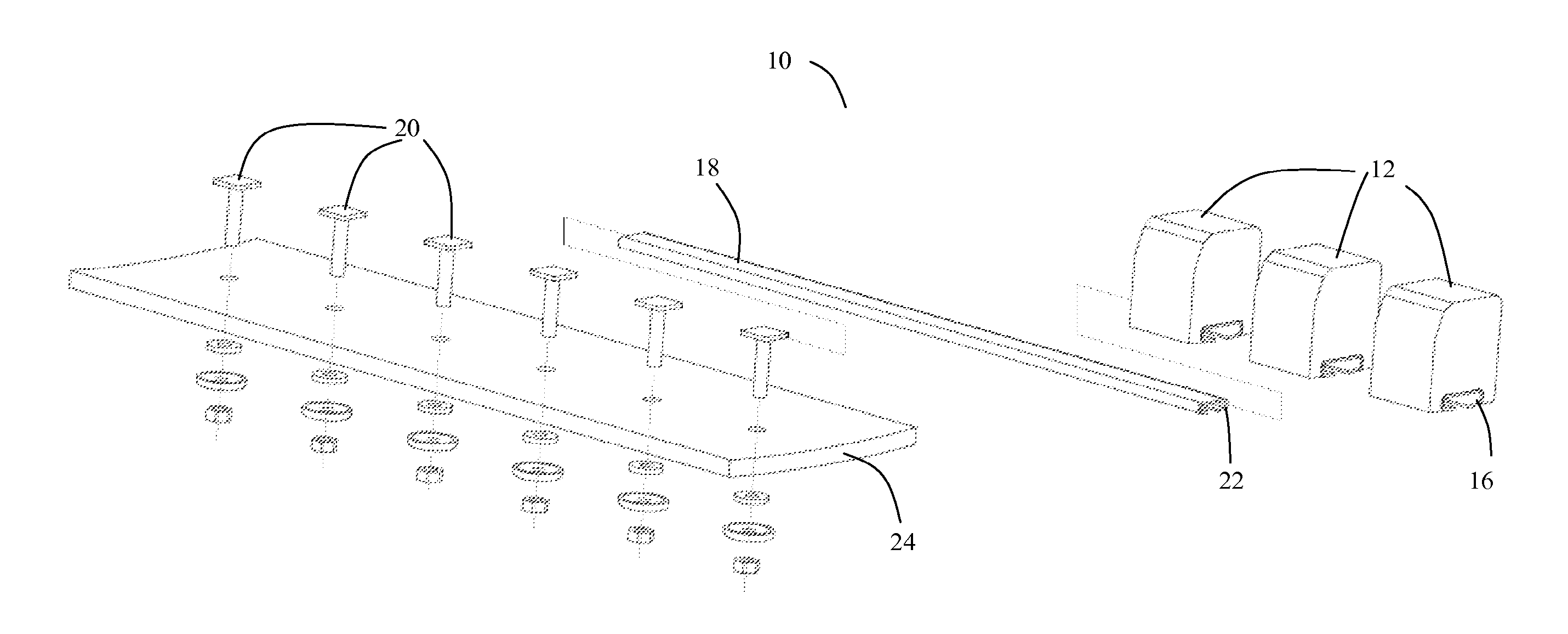
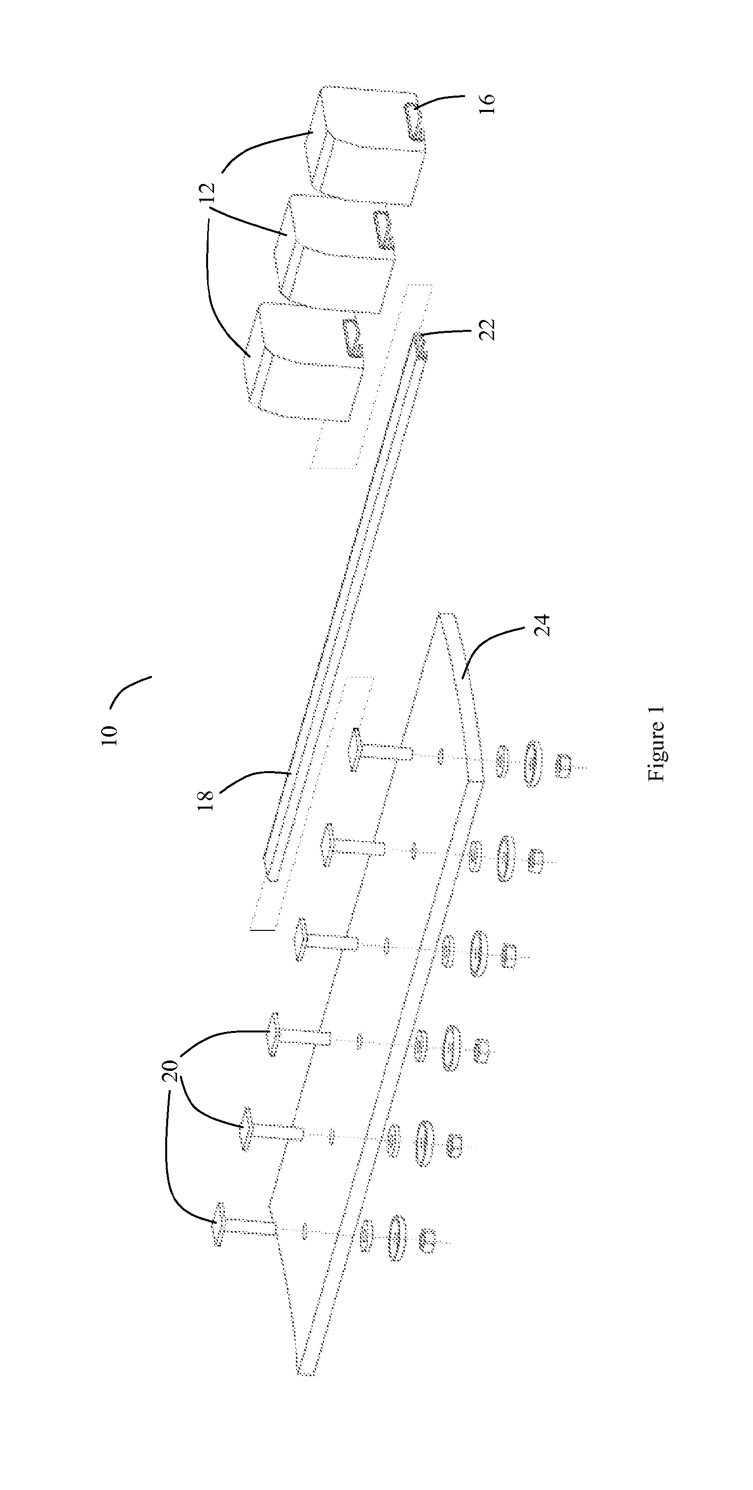
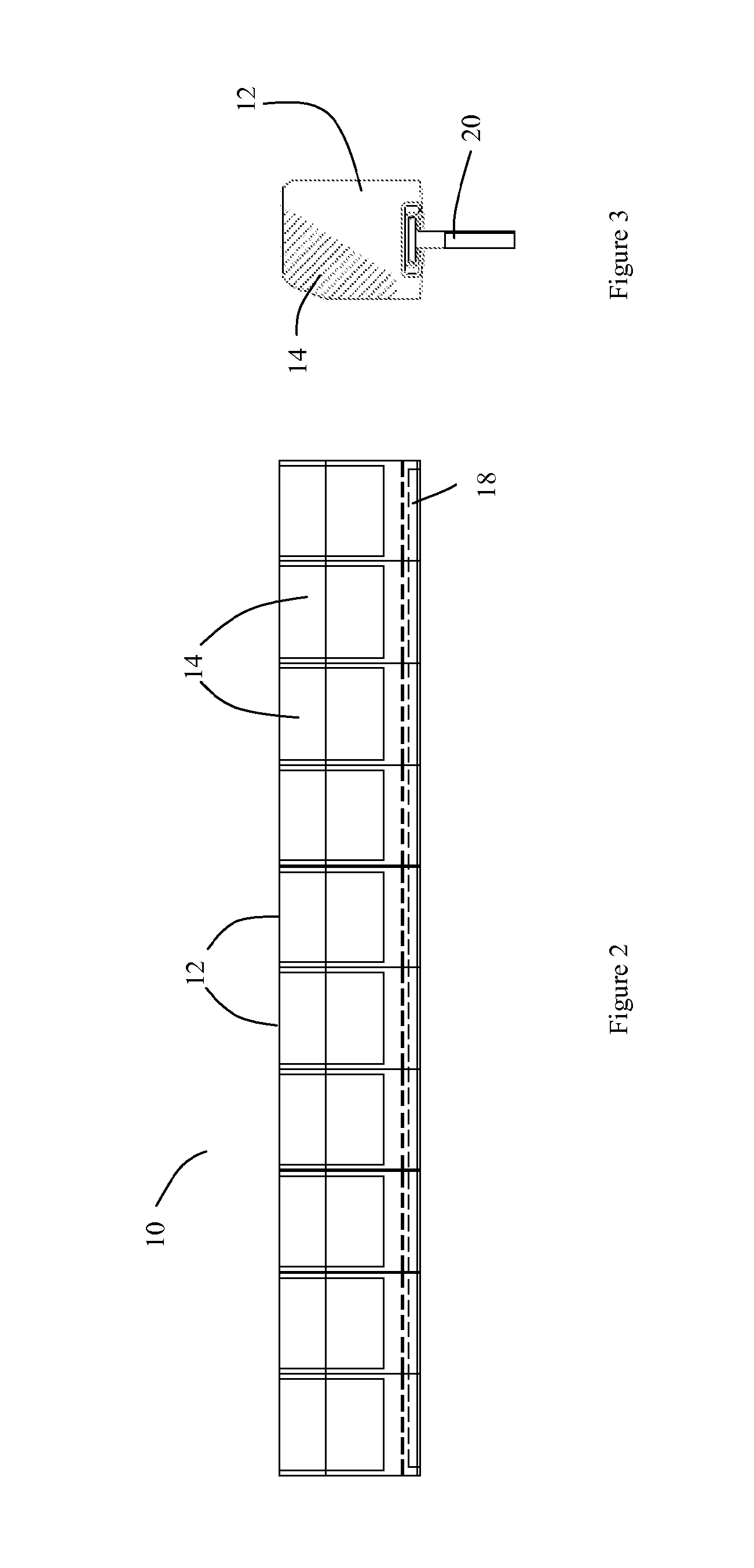
[0026]Referring to the figures, a lifter bar assembly 10 is shown including a number of block-like lifter bar segments 12, the segments being arranged to be installed adjacent to one another to form what is effectively a continuous, elongate lifter bar, as shown most clearly in FIG. 2. Each of the segments 12 is predominantly formed from rubber and includes a block-like metal cap portion 14 moulded and joined into the rubber (see FIG. 3) to provide additional wear resistance. The metal cap 14 is arranged at the in use uppermost front leading edge surface region of the lifter bar segment 12, where impact from grinding balls and mineral ore is greatest. Each of the segments 12 weighs approximately 40 kg.

[0027]The assembly 10 further includes an elongate member in the form of a T-shaped track 18. Each segment 12 includes a channel 16 which is dimensioned to be a sliding fit about T-track 18, to enable the segments 12 to be threaded onto T-track 18.

[0028]The T-track 18 is associated in ...


PUM

PropertyMeasurementUnit
Weightaaaaaaaaaa
Weightaaaaaaaaaa
Weightaaaaaaaaaa

Abstract

A lifter bar assembly for a crushing mill is disclosed including: a plurality of lifter bar segments; the segments being arranged to be installed adjacent to one another to form a lifter bar; wherein each of the segments are of a weight which can be safely handled by a team of two people.

Description

TECHNICAL FIELD[0001]The present invention relates to a lifter bar assembly for a crushing mill and a method of installing the lifter bar. The invention has particular application in mineral processing, power generation and general industrial crushing operations.BACKGROUND ART[0002]A typical grinding mill comprises a generally cylindrical drum with openings at one or both ends of the drum. Spaced about the inside wall of the drum are a number of lifter bars which are elongate objects which stand proud of the inner drum surface. The material to be ground is introduced to the drum along with grinding media in the form of a number of steel balls. The drum is caused to rotate and, as it does so, the lifter bars serve to lift the material and grinding media as the drum rotates, rather than merely sliding along the inside wall of the drum. At a certain point in the rotation of the drum, the material and grinding media falls away from the lifter bar by action of gravity to impact at the lo...

Claims


Application Information

Patent Timeline
IPC IPC(8): B02C17/22B02C17/00B23P17/00
CPCB02C17/1825B02C17/22Y10T29/49716Y10T29/49739B02C17/225
Inventor COX, TERRYWATT, DANIELHAZELL, GRAEME
Owner WEIR MINERALS AUSTRALIA LTD
Why Eureka
Eureka Blog
Learn More